创建组件识别数据的方法.pdf - 第139页
139/178 IM-SMT-VSNDI C-0002 -000 If the shape is a rectangle: The lead length x the lead width. If the shape is a circle, The lead lengt h = 0 (See Figure 1 14.) Note *2: The center of gravity of the object being detecte…

138/178
IM-SMT-VSNDIC-0002-000
Items to be set Set value
Explanation
Comp. Threshold
Sets the binarization level. (If 0 is
specified, the threshold is set
automatically.)
Comp. Tolerance
Specifies the tolerance of the shape as
a percentage.
Search Area (mm) Sets the range of the detection.
Body Size X (mm) Sets the size of the outer edge.
Body Size Y (mm) Sets the size of the outer edge.
Body Size Z (mm) Sets the size of the outer edge.
Cntr. Offset X (mm)
Sets the offset amount in the X direction
from the center position.
Cntr. Offset Y (mm)
Sets the offset amount in the Y direction
from the center position.
Cntr. Offset R (mm)
Sets the offset amount of the angle of
rotation.
Ruler Width 3 Not used.
Algorithm Special 2
Base Alignment As Mark
Vision Option 1 0
Vision Option 2 0
Vision Option 3 0
Vision Option 4
0
*3
Specifies the priority to perform “Cut
Inner Noise “/”Cut Outer Noise” function
and the object type.
Items to be set
Set
value
Explanation
Lead Group N 1
Common
Ruler Offset N --
Lead Number: 1N 1
Reflect LL.: 1N (mm)
*1
Lead Width: 1N (mm)
*1
Sets the size (surface area) of
the upper side.
Lead Pitch: 1N (mm) 0.0
Find Pos X: 1N (mm)
*2
N
direction
Group
1
Find Pos Y: 1N (mm)
*2
Sets the center of gravity
position of the upper side.
Lead Group S 1
Common
Ruler Offset S --
Lead Number: 1S 1
Reflect LL.: 1S (mm)
*1
Lead Width: 1S (mm)
*1
Sets the size (surface area) of
the lower side.
Lead Pitch: 1S (mm) 0.0
Find Pos X: 1S (mm)
*2
S
direction
Group
1
Find Pos Y: 1S(mm)
*2
Sets the center of gravity
position of the lower side.
Table 95
Note:
The parameters other than those shown in
Table 95
are not used.
Note *1: The size (surface area) of the object being detected is set to the “Reflect LL.” and
“Lead Width.” Field.
The diameter of the circle is specified by using the lead width as follows:

139/178
IM-SMT-VSNDIC-0002-000
If the shape is a rectangle: The lead length x the lead width.
If the shape is a circle, The lead length = 0
(See Figure 114.)
Note *2: The center of gravity of the object being detected is set at a position offset from the
component center. (See Figure 114. In the example, the “Find Pos X” is 0.)
Figure 114
Note *3. This option parameter consists of one byte of data, and each bit has different
meaning.
If the values of Noise Cut for the outside and inside of the component are specified as n1/n2,
the value obtained from the formula below is set:
If the object is white, n2 x 8 + n1
If the object is black, 64 + n2 * 8 + n1
For example, if the noise cut outside the component is executed twice and the noise cut
inside the component three times, the values obtained from the following formula are set:
If the object is white, 3x8 + 2 = 26
If the object is black, 64 + 3x8 + 2 = 90
Also, if the noise cut is executed first on the outside and then on the inside of the component,
the value subtract 128 from this value is set. In the above example,
If the object is white, 26 – 128 = -102
If the object is black, 90 – 128 = -38
The functions for cutting noise on both inside and outside of the component are used when
Body Size Y
Find Pos
Y
Find Pos Y
Lead Width
Lead Width= 0
Lead Length
Lead Width
Bit Position
The value of
“
Cut Outer Noise
”
: (0
-
7): n1
The value of
“
Cut Outer Noise
”
: (0
-
7): n2
Surface Type: (0: White, 1: Black)
Noise cut order: (0: Inner
Outer, 1: Outer
Inner)
Find Pos X
N1 = 0
Find Pos X
S1 = 0
Body Size X
140/178
IM-SMT-VSNDIC-0002-000
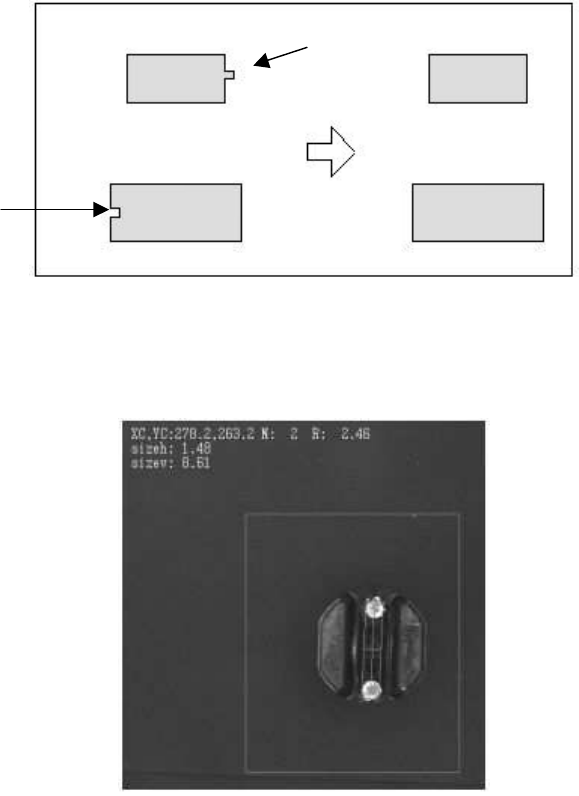
the noise is detected as shown in Figure 115, which eliminate the effects from the noise.
Please refer to “Appendix 1. Noise processing” for the details on the noise elimination
process.
Figure 115
In the actual example shown in
Figure 116
, the “Cut Outer Noise” function is used to eliminate
the effects caused by the projection on the lead section in order to stabilize the shape.
Figure 116
Also, if the component is divided into two parts and the boundary between the parts is not
clearly seen due to the lighting level, component lot, or another factor as shown in
Figure 117
,
the noise cut function can be used in order to perform stable recognition.
The “Cut Outer Noise” function separate the two objects connected together in order to
perform stable recognition.
“
Cut Inner Noise
”
“
Cut Outer Noise
”