创建组件识别数据的方法.pdf - 第124页
124/178 IM-SMT-VSNDI C-0002 -000 2.1 1.7. Special Recog ni tion of chip co mponent s (Cylindrical chip s) There are sev eral special r ecognition alg orithms available in the C ylindrical Chi p Recognition mode. (1) Spec…
123/178
IM-SMT-VSNDIC-0002-000
Figure 97
Special 11: Not supported
Special 12: Size Fitting (Bare chip )recognition
This is used for recognition of chip components. It detects the object whose size is
close to the defined component size by changing the threshold. It can also be used for
direction discrimination.
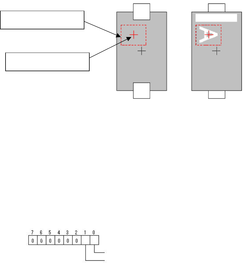
<Example of the setting for direction discrimination>
- Lead Group N: 2
- Number of the leads N2: Number of the brightness measurement area (circle)
- Lead Pitch N2: Pitch of the measurement area
- Lead Width N2: The diameter of the brightness measurement area (circle)
- Find Pos X: The coordinate of start point X in the brightness measurement area
- Find Pos Y: The coordinate of start point Y in the brightness measurement area
Option 1: Setting Flag
Option 2: The “Min. Brightness Difference” in the brightness measurement area
(When the value “0” is specified, the value “50” is adopted as default.)
Special 13: Not supported
Special 14: Not supported
Special 15: Check Many Adsorption
This detects whether more than one component is picked up by checking around
the detected chip component. The thickness of the actual component needs to be
input accurately as the distance to be checked varies depends on the component
thickness.
Determination area size Y
Determination area size X
Check Area Offset X
Check Area Offset Y
Bit position
Check Type: (0:Black, 1: White)
Check Direction: (0:
(0°, 180°), 1: (0°, 90°, 180°, 270°)
Picked up
properly
Not properly
picked up
124/178
IM-SMT-VSNDIC-0002-000
2.11.7. Special Recognition of chip components (Cylindrical chips)
There are several special recognition algorithms available in the Cylindrical Chip Recognition
mode.
(1) Special 1: Average brightness check in a object
If the outer periphery is brighter than the specified value, the result is satisfactory.
Option 1: The minimum value of difference between the brightness of outer periphery
and inner part
Option 2: The minimum brightness of inner part
Option 3: Cut Inner Noise
Option 4: Cut Outer Noise
(2) Special 2: Average brightness check in a object
If the outer periphery is darker than the specified value, the result is satisfactory.
Option 1: The maximum value of difference between the brightness of outer
periphery and inner part
Option 2: The maximum brightness of inner part
Option 3: Cut Inner Noise
Option 4: Cut Outer Noise
(3) Special 3: Center of gravity and shape constant check
This checks the shape constant.
Option 3: Cut Inner Noise
Option 4: Cut Outer Noise
The shape constant of a circle is obtained by dividing the square of the circumference
by the surface area, which becomes the constant of the certain value as shown below:
Peripheral length
2
/Surface area = (2 π r)
2
/ π r 2= 4 π
This value is calculated for the detected target, and is checked to see if it is within the
tolerance. (The surface area is also checked to see if it is within the tolerance.)
2.12. Special components
There are several mode available for recognition of special components.
1) Special Recognition mode
2) Odd. Chip Recognition mode
3) As Mark Recognition mode
4) Sp. Quad Recognition mode
5) Gravity mode
2.12.1. Special shapes
This recognition mode serves as the base for accommodating components with special
shapes. All of the component data shown in
Table 88
can be set.
Basically, this works as connector recognition, but it supports various types of recognition
depending on the base Alignment Type and algorithm(s) that are set.
For detailed information, please refer to the individual type of special recognition.

125/178
IM-SMT-VSNDIC-0002-000
<< Items to be set for special shapes >>
Items to be set Set value
Explanation
Alignment Group Special Sets the component category.
Alignment Type Special Sets the component type.
Comp. Threshold
Sets the difference of the detection level
for the lead detection.
Comp. Tolerance
Specifies the tolerance of the lead pitch
as a percentage.
Search Area (mm) Sets the range of the detection.
Body Size X (mm) Sets the size of the outer edge.
Body Size Y (mm) Sets the size of the outer edge.
Body Size Z (mm) Sets the size of the outer edge.
Cntr. Offset X (mm)
Sets the offset amount in the X direction
from the center position.
Cntr. Offset Y (mm)
Sets the offset amount in the Y direction
from the center position.
Cntr. Offset R (mm)
Sets the offset amount of the angle of
rotation.
Ruler Width
Algorithm
Selects the recognition algorithm when
using a special algorithm.
Base Alignment
Selects the basic component type when
using a special algorithm.
Vision Option 1 Sets option parameter 1.
Vision Option 2 Sets option parameter 2.
Vision Option 3 Sets option parameter 3.
Common
Data
Vision Option 4 Sets option parameter 4.
Items to be set
Set
value
Explanation
Lead Group N
Sets the number of the Lead
Group (1 or 2).
Common
Ruler Offset N
Sets the offset amount of the
detection line in the N direction.
Lead Number: 1N
Sets the number of leads of
Group 1 in the N direction.
Reflect LL.: 1N (mm)
Sets the lead length on the
image of Group 1 in the N
direction.
Lead Width: 1N (mm)
Sets the width of the leads of
Group 1 in the N direction.
Lead Pitch: 1N (mm)
Sets the lead pitch of Group 1 in
the N direction.
Find Pos X: 1N (mm)
Sets the reference position X for
the lead of Group 1 in the N
direction.
Group
1
Find Pos Y: 1N (mm)
Sets the reference position Y for
the lead of Group 1 in the N
direction.
Lead Number: 2N
Sets the number of leads of
Group 2 in the N direction.
N
direction
Group
2
Reflect LL.: 2N (mm)
Sets the lead length on the
image of Group 2 in the N
direction.