创建组件识别数据的方法.pdf - 第146页
146/178 IM-SMT-VSNDI C-0002 -000 Item s to be set Set value Lead Pitch: 2N ( mm) 0.0 Find Pos X: 2N (mm) 1.1 Find Pos Y : 2N (m m) 0.7 Lead Group S 2 Comm on Ruler Offset S 0 Lead Num ber: 1S 1 Reflect LL.: 1 S (mm) 1. 2…
145/178
IM-SMT-VSNDIC-0002-000
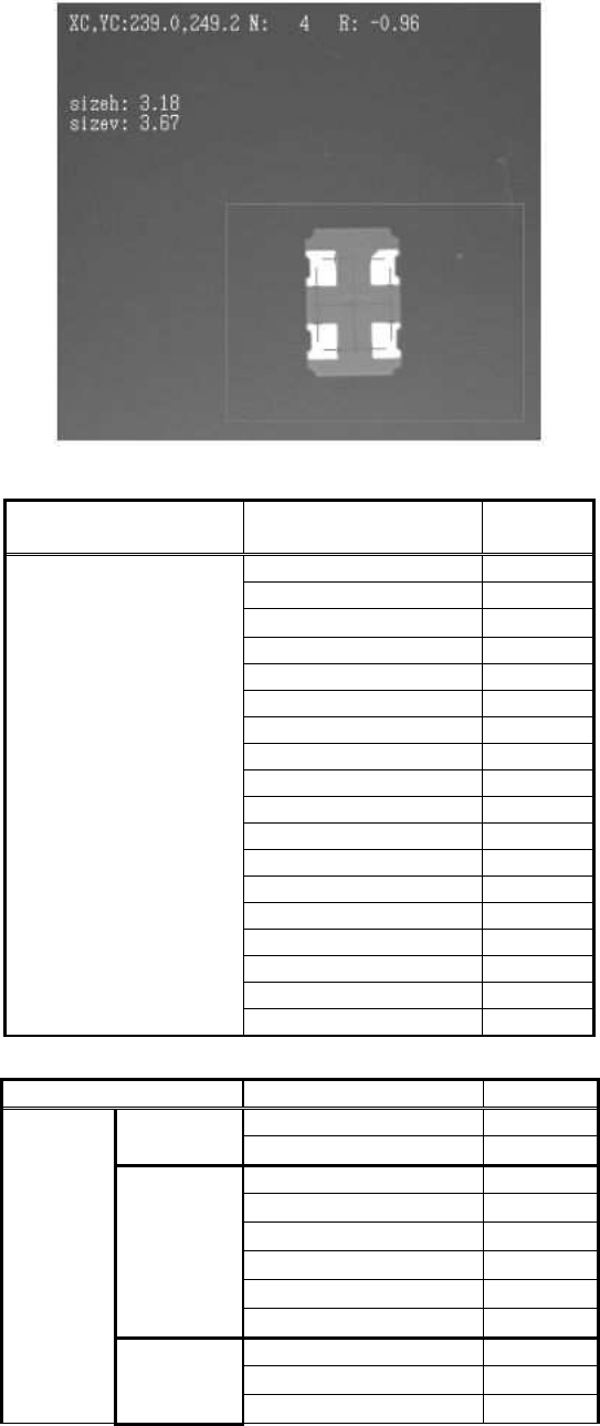
Figure 121
Items to be set
Set
value
Alignment Group Special
Alignment Type Special
Comp. Threshold 0
Comp. Tolerance 30
Search Area (mm) 3.0
Body Size X (mm) 3.2
Body Size Y (mm) 3.7
Body Size Z (mm) 0.5
Cntr. Offset X (mm) 0.0
Cntr. Offset Y (mm) 0.0
Cntr. Offset R (mm) 0.0
Ruler Width 1
Algorithm Special 3
Base Alignment As Mark
Vision Option 1 0
Vision Option 2 0
Vision Option 3 0
Common
Data
Vision Option 4 0
Items to be set Set value
Lead Group N 2
Common
Ruler Offset N 0
Lead Number: 1N 1
Reflect LL.: 1N (mm) 1.2
Lead Width: 1N (mm)
1.0
Lead Pitch: 1N (mm) 0.0
Find Pos X: 1N (mm) -1.1
Group
1
Find Pos Y: 1N (mm) 0.7
Lead Number: 2N 1
Reflect LL.: 2N (mm) 1.2
N
direction
Group
2
Lead Width: 2N (mm)
1.0
146/178
IM-SMT-VSNDIC-0002-000
Items to be set Set value
Lead Pitch: 2N (mm) 0.0
Find Pos X: 2N (mm) 1.1
Find Pos Y: 2N (mm) 0.7
Lead Group S 2
Common
Ruler Offset S 0
Lead Number: 1S 1
Reflect LL.: 1S (mm) 1.2
Lead Width: 1S (mm) 1.0
Lead Pitch: 1S (mm) 0.0
Find Pos X: 1S (mm) -1.1
Group
1
Find Pos Y: 1S(mm) -0.7
Lead Number: 2S 1
Reflect LL.: 2S (mm) 1.2
Lead Width: 2S (mm) 1.0
Lead Pitch: 2S (mm) 0.0
Find Pos X: 2S (mm) 1.1
S
direction
Group
2
Find Pos Y: 2S(mm) -0.7
Table 98
2.12.3-5. Mark – General purpose
This recognition mode is used for various components consisting of multiple parts, as shown
in
Figure 122
.
Figure 122
The target object is binarized, then the component is detected from the detected target object.
This mode can be used for recognition of the irregular shaped components.
It is possible to use the fixed threshold and the automatic threshold for binarization.
The tilt of the component is determined from the inclination of the straight lines which connect
the centers of each side.
White objects are normally recognized, but it is also possible to detect black objects on
a white background.
[Recognition check items]
Items Yes / No Notes
Body Size Yes
Lead pitch No
Lead width No
Lead length No
Lead position No
Table 99
<< Mark-General purpose : Items to be set for components consists of multiple parts >>
(Special components: Special shape, Algorithm: Special 4, Base Alignment Type: Mark type)

147/178
IM-SMT-VSNDIC-0002-000
Items to be set Set value
Explanation
Alignment Group Special Sets the component category.
Alignment Type Special Sets the component type.
Comp. Threshold
Sets the binarization level.
(If 0 is specified, the threshold is set
automatically.)
Comp. Tolerance Specifies the tolerance as a percentage.
Search Area (mm) Sets the range of the detection.
Body Size X (mm) Sets the size of the outer edge.
Body Size Y (mm) Sets the size of the outer edge.
Body Size Z (mm) Sets the size of the outer edge.
Cntr. Offset X (mm)
Sets the offset amount in the X direction
from the center position.
Cntr. Offset Y (mm)
Sets the offset amount in the Y direction
from the center position.
Cntr. Offset R (mm)
Sets the offset amount of the angle of
rotation.
Ruler Width 0 Not used.
Algorithm Special 4
Selects the recognition algorithm when
using a special algorithm.
Base Alignment As Mark
Selects the basic component type when
using a special algorithm.
Vision Option 1
*2
Sets option parameter 1.
Vision Option 2
*3
Sets option parameter 2.
Vision Option 3 0 Sets option parameter 3.
Common
Data
Vision Option 4
*1
Specifies the priority to perform “Cut
Inner Noise “/”Cut Outer Noise” function
and the object type.
(continued)
Note
*1
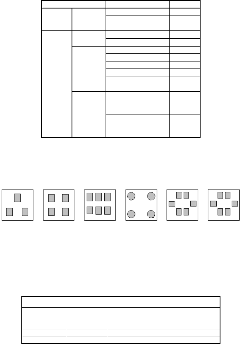
: This option parameter consists of one byte of data, and each bit has different
meaning. (Please refer to “2.12.3-3. Mark 2”, Note *3 for the details.)
Note
*2
: This option parameter consists of one byte of data, and each bit has different
meaning.
Bit position
Pitch check: (0: Not executed, 1: Executed)
Lead position check 0: Not executed 1: Executed.
(This checks to see if the lead is within the range specified
by the pitch x tolerance. If a check is carried out, the pitch
is input, even if there is only one lead.)
* Please refer to Appendix 4.
Method of setting the parameter for the distance between
the lead and
corner:
(
0: New 1: Previous
)
Trace retry: (0:No,
1: Yes)
The binarization method when the threshold is
0: Automatic binarizaiton, 1: P
-
tile binarization