创建组件识别数据的方法.pdf - 第47页
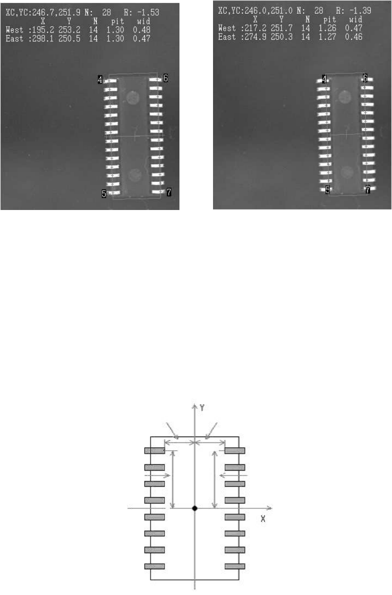
47/178 IM-SMT-VSNDI C-0002 -000 < Lead tip detect ion> <Lead root detection> Figure 41 As shown in Fig ure 41, in ins ide recognition m ode, th e inner portion of the detect ion leads (indicated b y the numbe…
46/178
IM-SMT-VSNDIC-0002-000
If the recognition is still not stable, Lead root recognition mode should be used.
In this mode, the root of the lead is recognized not the tip.
When this recognition mode is selected, either “Inside Recognition” or “Inside +
LeadAutoSearch” should be selected for ”Recognition Way” in the recognition parameters.
As shown in Figure 39, the lead tips look split and the roots where the leads are attached are
visible, which affect the recognition of SOJs.
In this case, Lead rood recognition mode provides the stable recognition by detecting the
inner leads.
Moreover, with the “Lead Auto Search”, the LeadPitch and LeadWidth parameters are used
when the row of leads is detected, and leads that match these definition data are picked out
during lead detection.
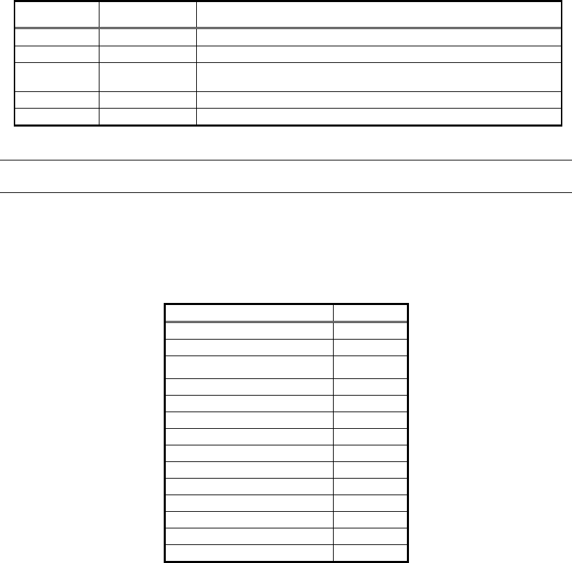
[Recognition check items]
Items Yes / No Notes
Body Size No
Lead pitch Yes The pitch in the direction with one lead is not checked.
Lead width
May exist
Checks only when the lead width is more than 1.0mm.
(Note 1)
Reflect LL No
Find Pos No
Table 29
Note:
1. “Lead width check” function may not be available for some old softwares.
The following is the actual example of the recognition of the normal lead tip detection and root
detection.
<<Items to be set for SOJs>>
Items to be set Set value
Alignment Group IC
Alignment Type SOJ
Comp. Threshold 50
Comp. Tolerance 30
Search Area (mm) 3.0
Body Size X (mm) 8.64
Body Size Y (mm) 18.42
Body Size Z (mm) 3.50
Ruler Offset 6
Ruler Width 3
Lead Number 14
Reflect LL. (mm) 1.80
Lead Width (mm) 0.43
Lead Pitch (mm) 1.27
Table 30
When performing inside recognition, it may not be able to detect the component without
inputting the correct Lead length. Please check the display of the defined shape to make sure
it matches to the actual component.
47/178
IM-SMT-VSNDIC-0002-000
< Lead tip detection> <Lead root detection>
Figure 41
As shown in Figure 41, in inside recognition mode, the inner portion of the detection leads
(indicated by the number 4 through 7 in the figures) are detected.
2.5.1. Special recognition in the SOJ Recognition mode
There is no special recognition in SOJ recognition mode at this point in time.
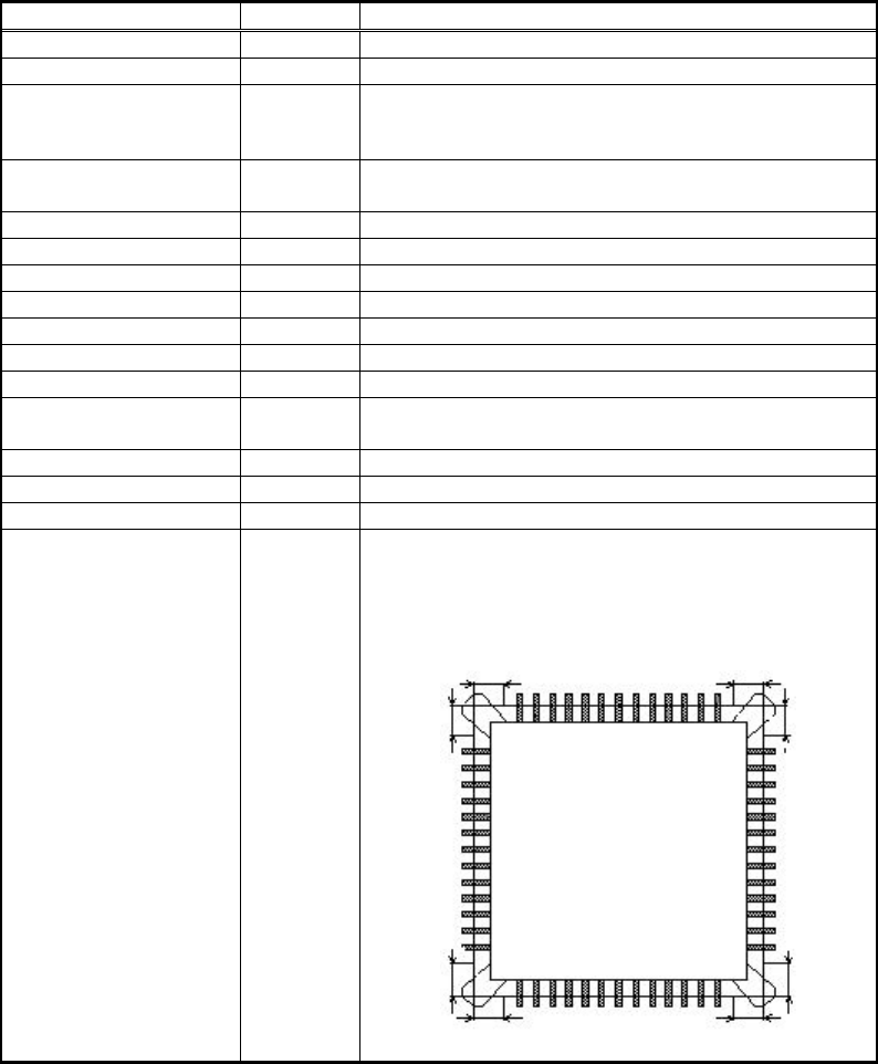
[How to set the “Find Pos” when the Rood Detection mode is used]
In the Root Detection mode, the root position of the lead is internally set as the reference lead
position (Find Pos). (See Figure 42).
As these are set internally in the software, the users basically do not need to consider.
However, please keep it in mind when using the Special Recognition mode.
Figure 42
Find Pos X E1
Find Pos X W1
Find Pos Y E1
Find Pos Y W1
48/178
IM-SMT-VSNDIC-0002-000
2.6. QFPs
Setting the data in Table 31 is required to create the component data of QFP components.
<Items to be set for QFPs>
Items to be set Set value
Explanation
Alignment Group IC Sets the component category.
Alignment Type QFP Sets the component type.
Comp. Threshold
Sets the detection level difference for lead
detection.
(See “Appendix 2. Detection level
differences used to detect leads (threshold value)”.)
Comp. Tolerance
Specifies the tolerance of lead pitch as a
percentage.
Search Area (mm) Sets the range of the detection.
Body Size X (mm) Sets the size of the outer edge.
Body Size Y (mm) Sets the size of the outer edge.
Body Size Z (mm) Sets the size of the outer edge.
Ruler Offset Sets the offset amount for the detection line.
Ruler Width
Lead Number N
Sets the number of leads in the cross direction.
Lead Number E
Sets the number of leads in the lengthwise
direction.
Lead Pitch (mm)
Sets the lead pitch.
Lead Width (mm)
Sets the width of the lead.
Reflect LL. (mm)
Sets the lead length on the image.
Bumper Mask (mm)
When the QFP has bumpers, it sets so that the
range from the intersection point of the detection
lines and the set value are not to be detected.
( Normally, 0 is set for QFPs.)
Table 31