创建组件识别数据的方法.pdf - 第19页
19/178 IM-SMT-VSNDI C-0002 -000 2) 4-direction Co nnector rec ognition m ode 3) Odd-shape Co nnector recognition m ode <Ball components> 1) Simple BG A Recognition m ode 2) BGA Rec ognition m ode 3) Flip-chip Recog…
18/178
IM-SMT-VSNDIC-0002-000
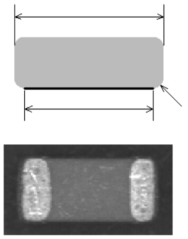
1.4.2. Component sizes (chip component)
When the chip component (capacitors) and other components whose tip is rounded, the
component size on the image may be different from the actual component size.
In this case, the size on the image should be set.
Figure 11
2. Details of the component data setting
As already mentioned, it is possible to create the data for the standard components with the
minimum necessary data.
In the component recognition mode, the components are divided into the groups shown below
and the data is created for each mode.
<IC components>
1) 2-pin components
2) Mini-mold transistors / SOTs
3) Power transistors
4) SOP Recognition mode
5) QFP Recognition mode
6) SOJ Recognition mode
7) PLCC Recognition mode
8) Off Lead
<Connector components>
1) Single-direction Connector recognition mode
Actual component size
Set component size
The fig
ure seen from the side of the component
This part looks dark
The image of the component seen from the bottom surface
19/178
IM-SMT-VSNDIC-0002-000
2) 4-direction Connector recognition mode
3) Odd-shape Connector recognition mode
<Ball components>
1) Simple BGA Recognition mode
2) BGA Recognition mode
3) Flip-chip Recognition mode
<Chip components>
1) Standard Chip Recognition mode
2) MELF Chip Recognition mode
3) Bare Chip Recognition mode
4) Circular Chip Recognition mode
5) Special Chip Recognition mode
6) Small Chip Recognition mode
<Special components>
1) Special Shape Recognition mode
2) Odd-shape Chip Recognition mode
3) Mark Recognition mode
4) Sp Quad Recognition mode
5) Center of Gravity Detection mode
The following section describes the items to be set and other information pertaining to the
individual recognition modes.
2.1. 2-pin components
<Items to be set for 2-pin components>
Items to be set Set value
Explanation
AlignmentGroup IC Sets the component category.
Alignment Type 2Ends Sets the component type.
Comp. Threshold
Sets the detection level difference for lead
detection.
(See “Appendix 2. Detection level differences
used to detect leads (threshold value))”
Comp. Tolerance
Specifies the shape tolerance as a percentage.
Search Area (mm)
Sets the range for detection.
Body Size X (mm)
Sets the outer edge size.
Body Size Y (mm)
Sets the outer edge size.
Body Size Z (mm)
Sets the outer edge size.
Ruler Offset
Sets the offset amount for the detection line.
Ruler Width
Reflct LL
Sets the lead length on the image.
Lead Width (mm)
Sets the lead width.
Table 6
This mode is used for recognition of components that have two leads, and for diodes,
aluminum capacitors and other components.
20/178
IM-SMT-VSNDIC-0002-000
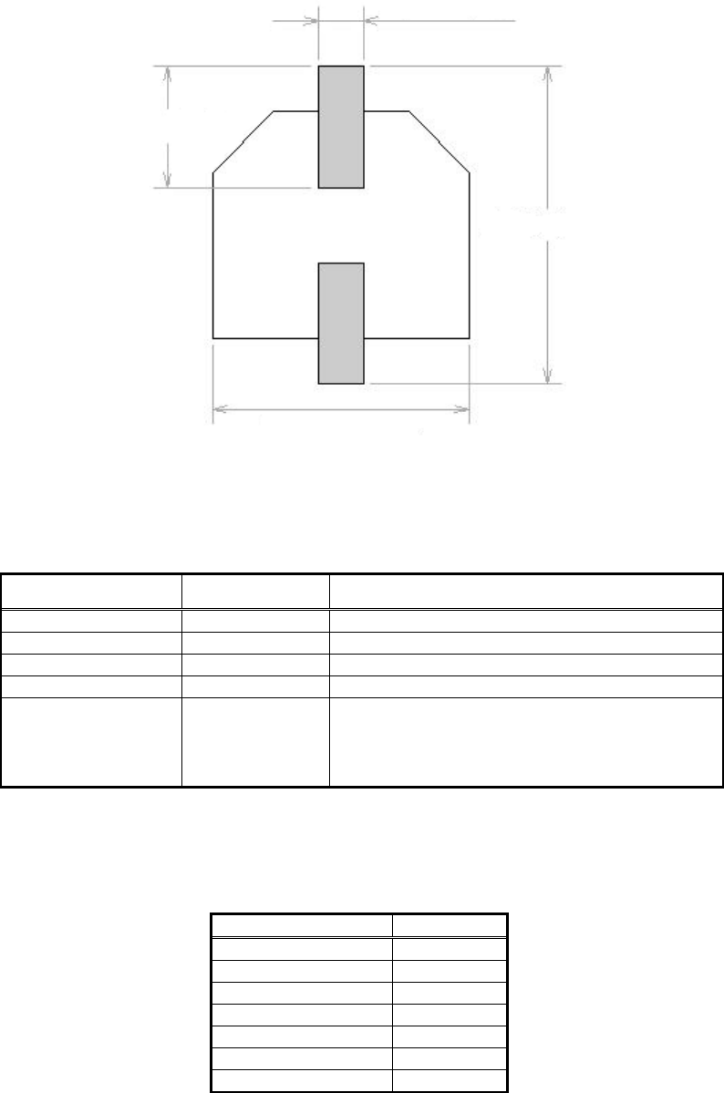
As shown in
Figure 12
, the components whose “Body size X” and the “Lead width” are different
can be defined. The upper/lower and left/right leads need to be symmetrical.
Chip recognition is used as the recognition method.
Figure 12
<Recognition check items>
Items Yes/No Notes
Body Size May exist Only “Body Size Y” is checked.
Lead pitch No
Lead width Yes
Lead length No
Lead position Yes
Checks the lead tip position using [Body Size
Y x tolerance] as the check range.
* Please refer to “Appendix 4. Lead position check”
for the details of “Lead position check” function.
Table 7
Table 8 is the example of actual settings and the recognition results. Please refer to
“Appendix
5. Reading and interpreting the recognition results display”
for how to interpret the information on
recognition result.
Items to be set Set value
Alignment Group IC
Alignment Type 2Ends
Comp. Threshold 50
Comp. Tolerance 30
Search Area (mm) 2.5
Body Size X (mm)
0.6
Body Size Y (mm)
7.6
Lead width
Lead length
Body size Y
Body size X