创建组件识别数据的方法.pdf - 第131页
131/178 IM-SMT-VSNDI C-0002 -000 Items to be set Set value Explanat ion Surface T y pe Selects from r eflecting component or non-reflect ing component. If the compone nt looks white, select “Reflecting com ponent”, if n …
130/178
IM-SMT-VSNDIC-0002-000
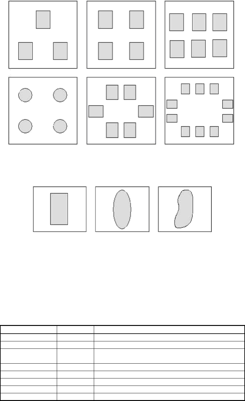
Figure 102
2.12.3-1. Mark 1
This is used for recognition of objects that consist of a single part as shown in
Figure 103
.
Figure 103
The target object is binarized, then the component is detected from the detected target object.
This mode can be used for recognition of the irregular shaped components.
It is possible to use the fixed threshold and the automatic threshold for binarization.
The component center is determined to be the center of gravity position, and the inclination
is determined to be the inclination of the axis.
The correct inclination of components that are close to the circular or square shape cannot be
obtained as they have no main axis.
White objects are normally recognized, but it is also possible to detect black objects on
a white background.
<< Items to be recognized for Mark 1 marks >>
Items to be set Set value Explanation
Alignment Group Special Sets the component category.
Alignment Type Mark Sets the component type.
Comp. Threshold
Sets the binarization level.
(If 0 is specified, the threshold is set automatically.)
Comp. Tolerance Specifies the tolerance of the shape as a percentage.
Search Area (mm)
Sets the range of the detection.
Body Size X (mm)
Sets the size of the outer edge.
Body Size Y (mm)
Sets the size of the outer edge.
Body Size Z (mm)
Sets the size of the outer edge.
131/178
IM-SMT-VSNDIC-0002-000
Items to be set Set value Explanation
Surface Type
Selects from reflecting component or non-reflecting
component. If the component looks white, select
“Reflecting component”, if not, select “Non reflecting
component”.
Cut Outer Noise Select from 0 through 7.
Cut Inner Noise Select from 0 through 7.
Noise Cut Order “Inner” / “Outer”
Table 91
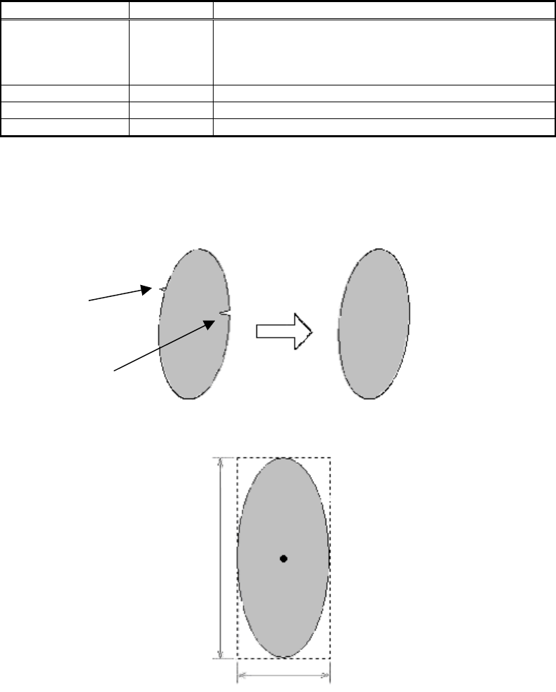
The functions for cutting noise both inside and outside the component are used when the
noise is detected as shown in
Figure 104
, which eliminate the effects from the noise.
Please refer to ”Appendix 1. Noise processing” for the details of the noise elimination process.
Figure 104
Figure 105
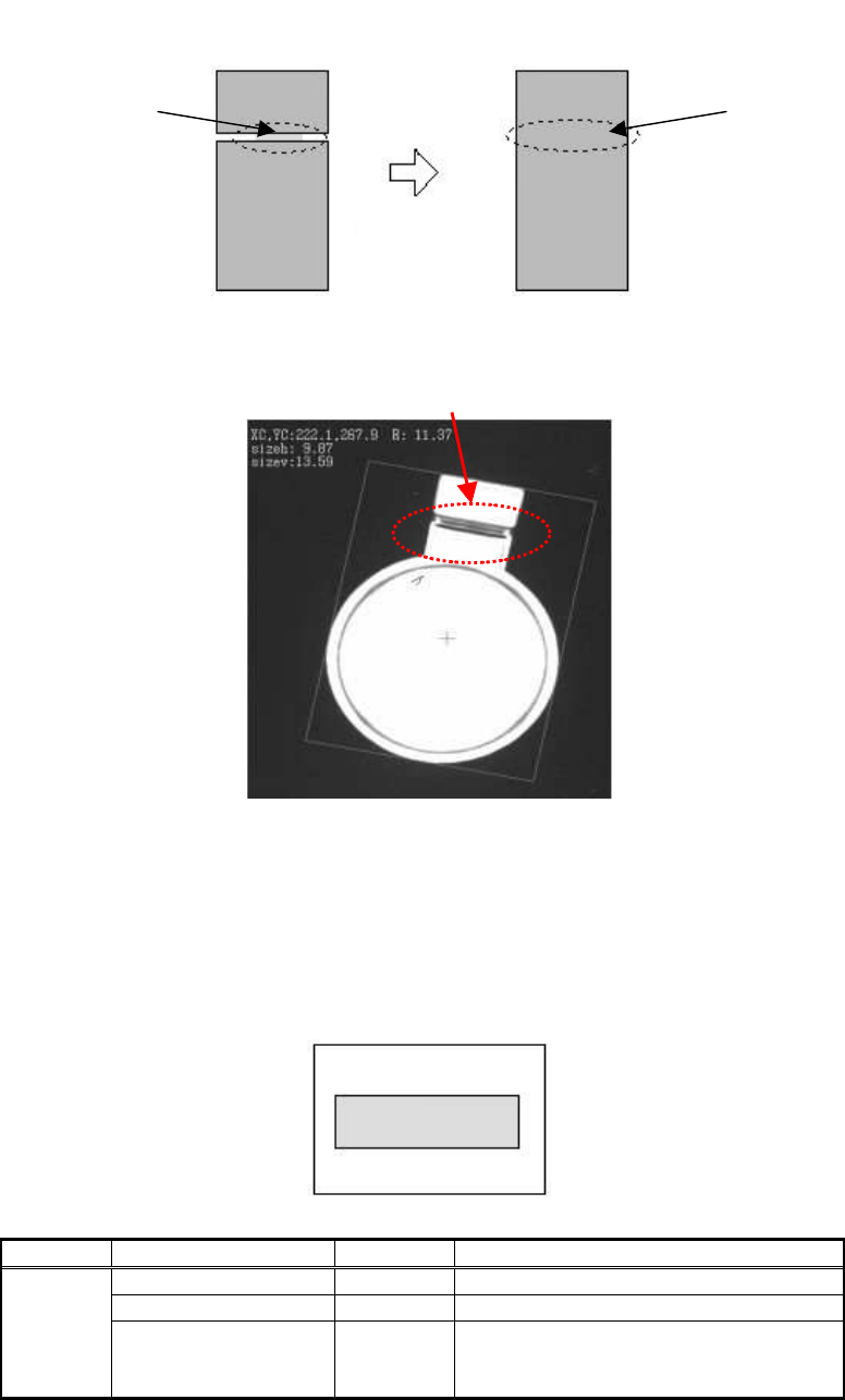
Also, if the component is divided into two parts and the boundary between the parts is not
clearly seen due to the lighting level, component lot, or another factor as shown in
Figure 106
(the figure on the left), the noise cut function can be used in order to perform stable
recognition.
In the example in
Figure 106
, the “Cut Inner Noise” function is used in order to perform the
stable recognition by combining the two separate objects together.
“Cut Outer Noise”
“Cut Inner Noise”
Body Size Y
Body Size X
132/178
IM-SMT-VSNDIC-0002-000
Figure 106
In the actual example shown in Figure 107, the “Cut Outside Noise” function prevents the lead
part and body part from separating each other in order to perform stable recognition.
Figure 107
2.12.3-2. Mark Line
This is used to recognize rectangles consisting of a single part, as shown in Figure 108.
Components are detected from among objects that have been binarized and detected. Either
fixed or automatic threshold values can be used for the binarization. The component center
and inclination are determined by setting the detection line. White objects are normally
recognized, but it is also possible to detect black objects on a white field.
Figure 108
Items to be set Set value
Explanation
Alignment Group Special
Alignment Type Special
Common
Data
Comp. Threshold
Sets the binarization level. (If 0 is
specified, the threshold is set
automatically.)
This part cannot be
seen clearly.
Combined
“Cut Inner
Noise” function