创建组件识别数据的方法.pdf - 第113页
113/178 IM-SMT-VSNDI C-0002 -000 [Recognition check items ] Items Y es / No Notes Body Size Ma y exist Only Body Size Y is checked Lead pitch No Lead width Y es Lead position No Find Pos Y es Checks w hether the center o…
112/178
IM-SMT-VSNDIC-0002-000
2.11.1. Standard chips
<<Items to be set for standard chips>>
Items to be set Set value Explanation
Alignment Group Chip Sets the component category.
Alignment Type Std. Chip Sets the component type.
Comp. Threshold
Sets the detection level difference for lead
detection.
Note1.
(
See “Appendix 2. Detection level differences used to
detect leads (threshold value)”.)
Comp. Tolerance Specifies the tolerance as a percentage.
Search Area (mm) Sets the range of the detection.
Body Size X (mm) Sets the size of the outer edge.
Body Size Y (mm) Sets the size of the outer edge.
Body Size Z (mm) Sets the size of the outer edge.
Ruler Offset Sets the offset amount for the detection line.
Table 76
Note1:
If the Comp Threshold is set to 0, a threshold value is set automatically. At the same time, a
check (“Symmetry”) is performed to see if the brightness at the center of the component has
changed.
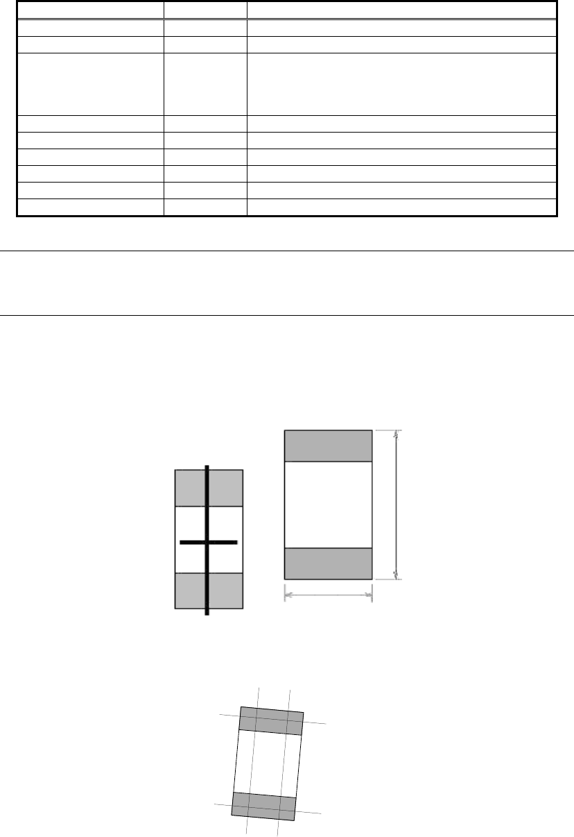
In “Symmetry” check, the brightness is checked on the 2 straight lines that pass through the
center point of the chip as shown in Figure 84.
On the horizontal line, it checks if the brightness change is small.
On the vertical line, it checks if the brightness change at the upper and lower ends of the chip
are symmetrical.
Figure 84
The detection lines are drawn in “#” shape. If the lines need to be drawn in “‡” shape, MELF
chip should be selected.
Figure 85
Body Size Y
Body Size X
113/178
IM-SMT-VSNDIC-0002-000
[Recognition check items]
Items Yes / No Notes
Body Size May exist Only Body Size Y is checked
Lead pitch No
Lead width
Yes
Lead
position
No
Find Pos Yes
Checks whether the center of the detected lead tip is in
the range of Body Size Y x tolerance.
Nozzle
check
*Note 1
Yes
“Lead Brightness” check.
*Note 2
“Symmetry” check (Only when the threshold is set to 0.)
*Note 3
Table 77
Note 1:
“Nozzle check” is the function for detecting the components that have not been picked up.
When there is a component that has not been picked up and if the nozzle is contaminated
with solder, please make sure that the solder adhered to the nozzle is not falsely recognized
as a component.
Note 2:
The “Lead Brightness” function checks if the brightness of the electrode section of the chip is
smaller than the specified value. If it is smaller, it is detected to be an error.
Note 3:
“Symmetry check” (Described above).
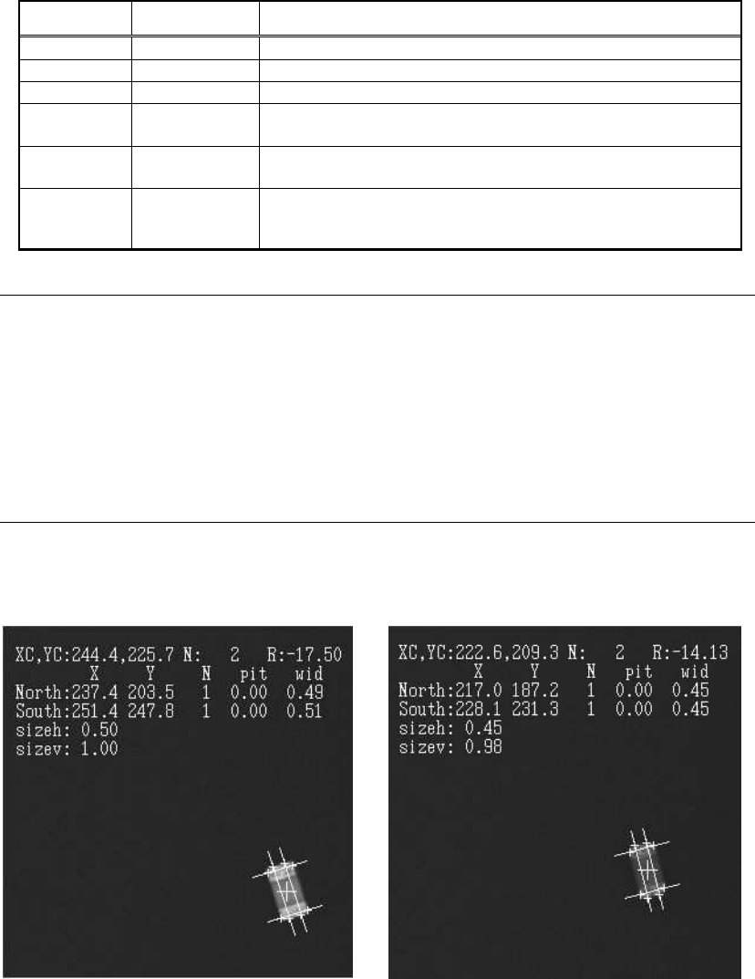
The following is the actual example of the recognition.
<<Recognition result of R1005>> <<Recognition result of C1005>>
Figure 86
As can be seen from the figures, in the recognition of the resistor (R1005), the component
size is approximately equivalent to the size of actual component. However in the recognition
of the capacitor (C1005), the size of the detected component is slightly smaller than the actual
size. This is because the ends of the capacitor are rounded, which makes the component look
smaller on the image. In cases like this, the user should specify the size on the image.
(Please refer to “1.4.Precautions concerning the component data definitions”.)
114/178
IM-SMT-VSNDIC-0002-000
2.11.2
MELF chips
<<Items to be set for MELF chips>>
Items to be set Set value Explanation
Alignment Group Chip Sets the component category.
Alignment Type MELF chip Sets the component type.
Comp. Threshold
Sets the detection level difference for lead
detection.
(See “Appendix 2. Detection level differences used to
detect leads (threshold value)”.)
Comp. Tolerance Specifies the shape tolerance as a percentage.
Search Area (mm) Sets the range of the detection.
Body Size X (mm) Sets the size of the outer edge.
Body Size Y (mm) Sets the size of the outer edge.
Body Size Z (mm) Sets the size of the outer edge.
Ruler Offset Sets the offset amount for the detection line.
Lead Width (mm) Sets the lead width.
Table 78
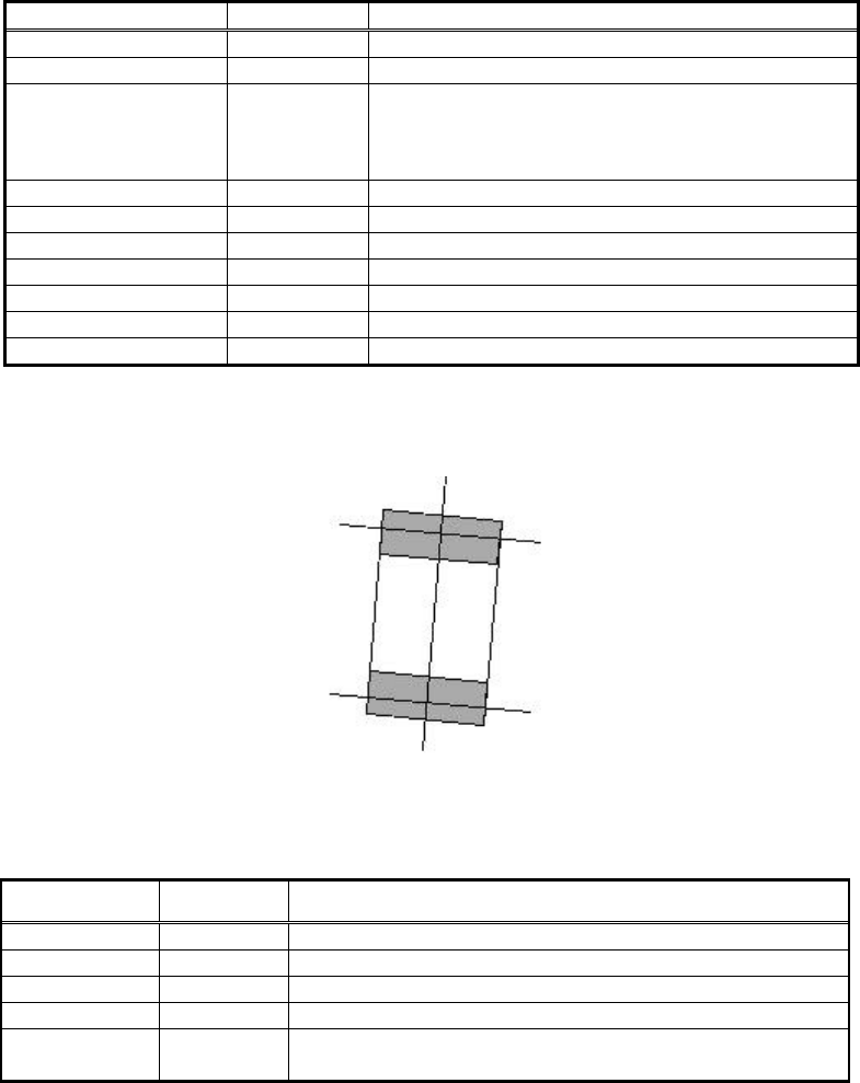
The detection line is drawn in “‡” shape.
Figure 87
[Recognition check items]
Items Yes / No Notes
Body Size May exist
Only Body Size Y is checked
Lead pitch No
Lead width Yes
Lead length No
Lead position
Yes
Checks whether the center of the detected lead tip is in
the range of Body Size Y x tolerance.
Table 79