创建组件识别数据的方法.pdf - 第111页
111/178 IM-SMT-VSNDI C-0002 -000 Figure 82 shows the definition sha pe. Figure 82 Figure 83 sho ws the recog nition result obtained b y the data. Figure 83 2.1 1 Chip component s There are a num ber of modes for chip rec…
110/178
IM-SMT-VSNDIC-0002-000
detection. Consequently, they should be defined as close to the outer edge as possible
within the various quadrants. (The user do not need to concern about making these positions
precisely.) It is possible to perform recognition by using Pos1 ~ 4, or Pos5 ~ 8.
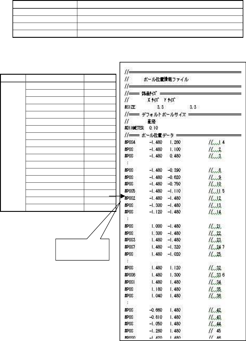
<< Commands for bump position definition >>
Command Items to be set
#SIZE Sets the size of the component.
#DIAMETER Sets the default ball diameter.
#POS Sets the ball position.
#POS 0 – #POS 7 Sets the reference ball position.
Table 75
The following is the actual example of recognition.
<<Flip chip Special 2 and 3>>
Figure 81
Items to be set Set value
Alignment Group Special
Alignment Type Special
Comp. Threshold 0
Comp. Tolerance 30
Search Area (mm) 0.5
Body Size X (mm) 3.5
Body Size Y (mm) 3.5
Body Size Z (mm) 0.5
Cntr. Offset X (mm)
0.0
Cntr. Offset Y (mm)
0.0
Cntr. Offset R (mm)
0.0
Ruler Width 0
Algorithm Special 2
Base Alignment Flip chip
Vision Option 1 126
Vision Option 2 0
Vision Option 3 0
Common
Data
Vision Option 4 0
File specified by
this number.
111/178
IM-SMT-VSNDIC-0002-000
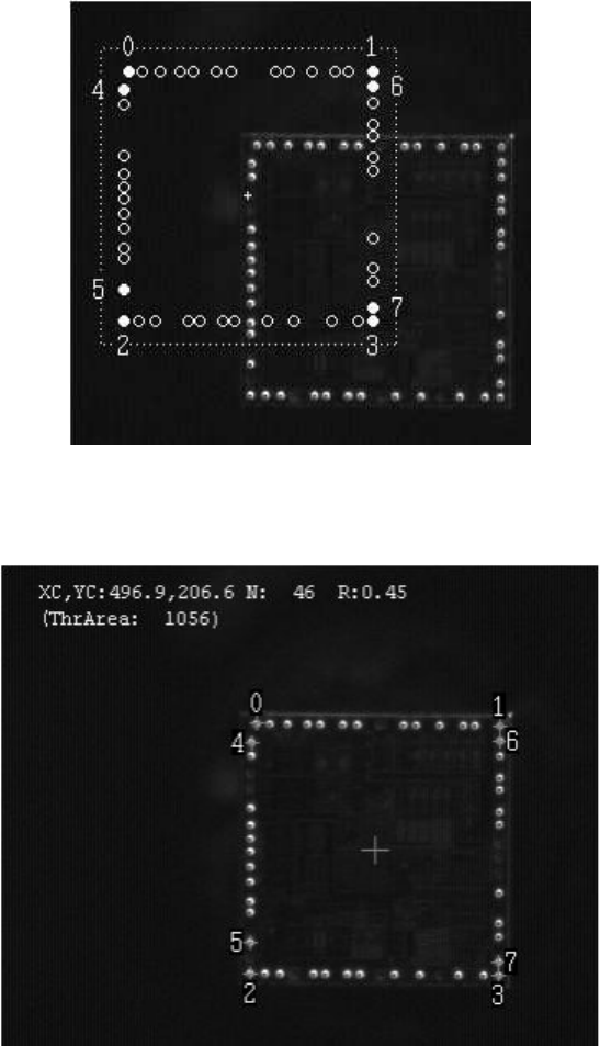
Figure 82
shows the definition shape.
Figure 82
Figure 83 shows the recognition result obtained by the data.
Figure 83
2.11 Chip components
There are a number of modes for chip recognition.
1) Standard Chip Recognition mode
2) MELF Chip Recognition mode
3) Bare Chip Recognition mode
4) Cylindrical Chip Recognition mode
5) Special Chip Recognition mode
6) Small Chip Recognition mode
112/178
IM-SMT-VSNDIC-0002-000
2.11.1. Standard chips
<<Items to be set for standard chips>>
Items to be set Set value Explanation
Alignment Group Chip Sets the component category.
Alignment Type Std. Chip Sets the component type.
Comp. Threshold
Sets the detection level difference for lead
detection.
Note1.
(
See “Appendix 2. Detection level differences used to
detect leads (threshold value)”.)
Comp. Tolerance Specifies the tolerance as a percentage.
Search Area (mm) Sets the range of the detection.
Body Size X (mm) Sets the size of the outer edge.
Body Size Y (mm) Sets the size of the outer edge.
Body Size Z (mm) Sets the size of the outer edge.
Ruler Offset Sets the offset amount for the detection line.
Table 76
Note1:
If the Comp Threshold is set to 0, a threshold value is set automatically. At the same time, a
check (“Symmetry”) is performed to see if the brightness at the center of the component has
changed.
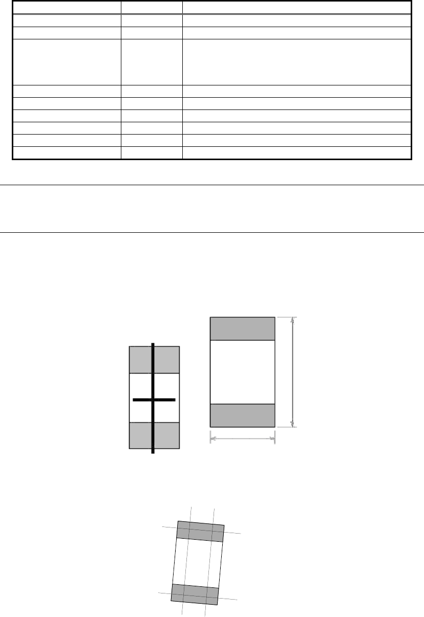
In “Symmetry” check, the brightness is checked on the 2 straight lines that pass through the
center point of the chip as shown in Figure 84.
On the horizontal line, it checks if the brightness change is small.
On the vertical line, it checks if the brightness change at the upper and lower ends of the chip
are symmetrical.
Figure 84
The detection lines are drawn in “#” shape. If the lines need to be drawn in “‡” shape, MELF
chip should be selected.
Figure 85
Body Size Y
Body Size X