创建组件识别数据的方法.pdf - 第76页
76/178 IM-SMT-VSNDI C-0002 -000 Figure 58 As described a bove, som etimes “S pecial 1” m ode does not provide s table recognition. W hen the leads for securing the connector are located close to the targeted le ads, dete…
75/178
IM-SMT-VSNDIC-0002-000
Option 3: Recognition flag
Option 4: Allowable length error (set as a value in units of 1/10 mm).
Values to be set are those between 0 and 255 (0.1 ~ 25.5 mm).
It does not perform check when the value is 0.
(When setting the value larger than 128, please input the value that 256 is
subtracted from the set value.)
The following is the actual example of the setting and the recognition result.
<<Items to be set for Special 1 connectors>>
Items to be set Set value
Alignment Group Special
Alignment Type Special
Comp. Threshold 50
Comp. Tolerance 30
Search Area (mm) 5.0
Body Size X (mm) 7.0
Body Size Y (mm) 15.0
Body Size Z (mm) 2.0
Cntr. Offset X (mm) 0.0
Cntr. Offset Y (mm) 0.0
Cntr. Offset R (mm) 0.0
Ruler Width 3
Algorithm Special 1
Base Alignment Special
Vision Option 1 0
Vision Option 2 0
Vision Option 3 0
Common
Data
Vision Option 4 0
Lead Group E 1
Common
Ruler Offset E 5
Lead Number: 1E 10
Reflect LL.: 1E (mm) 1.0
Lead Width: 1E (mm) 0.2
Lead Pitch: 1E (mm) 1.0
Find Pos X: 1E (mm) 3.5
E
Direction
Group 1
Find Pos Y: 1E (mm) 4.5
Table 51
Bit
position
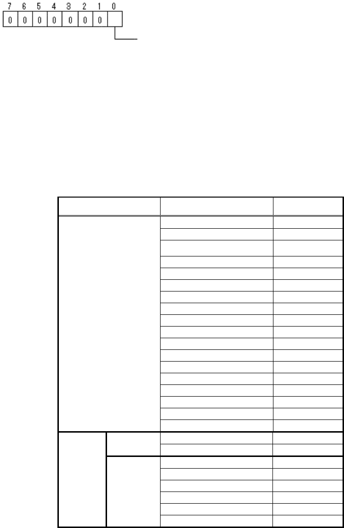
Excessive Lead Check (0:Non, 1:Exist)
(It checks whether the extra leads exist outside of pitch 1)
76/178
IM-SMT-VSNDIC-0002-000
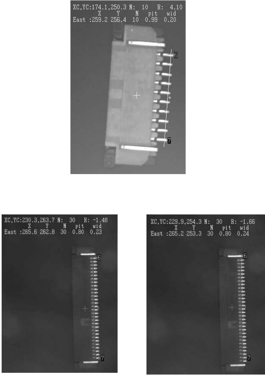
Figure 58
As described above, sometimes “Special 1” mode does not provide stable recognition.
When the leads for securing the connector are located close to the targeted leads, detection
error may occur as shown in Figure 59.
Figure 59
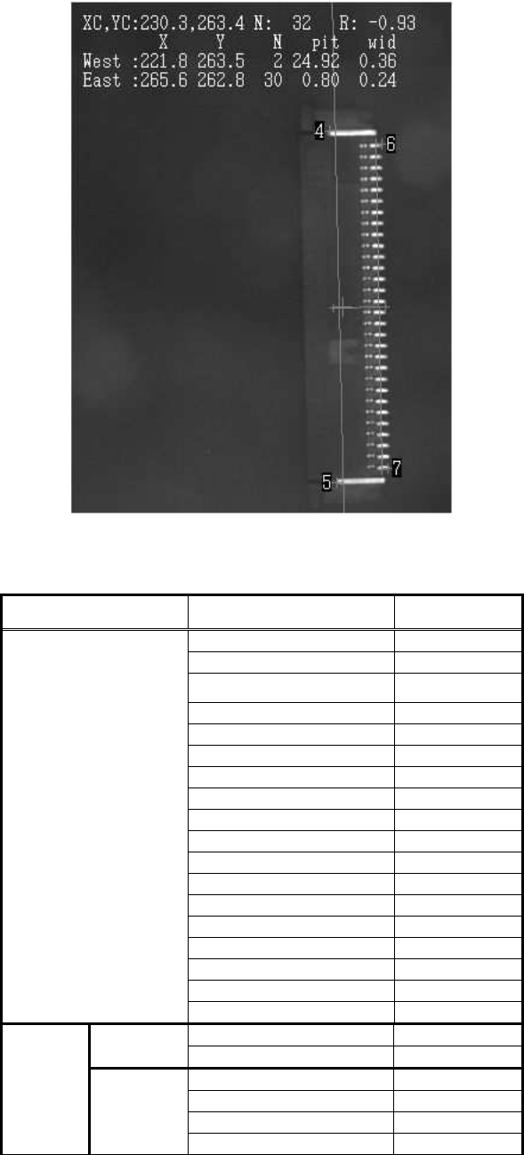
In this case, stable recognition can be performed by including leads used to secure
connectors as the target in the recognition process as shown in
Figure 60.
77/178
IM-SMT-VSNDIC-0002-000
Figure 60
<<Items to be set for Special 1 connectors>>
Items to be set Set value
Alignment Group Special
Alignment Type Special
Comp. Threshold 50
Comp. Tolerance 30
Search Area (mm) 5.0
Body Size X (mm) 7.0
Body Size Y (mm) 15.0
Body Size Z (mm) 2.0
Cntr. Offset X (mm) 0.0
Cntr. Offset Y (mm) 0.0
Cntr. Offset R (mm) 0.0
Ruler Width 3
Algorithm Special 1
Base Alignment Special
Vision Option 1 0
Vision Option 2 0
Vision Option 3 0
Common
Data
Vision Option 4 0
Lead Group E 1
Common
Ruler Offset E 5
Lead Number: 1E 30
Reflect LL.: 1E (mm) 0.5
Lead Width: 1E (mm) 0.2
E
Direction
Group 1
Lead Pitch: 1E (mm) 0.8