创建组件识别数据的方法.pdf - 第15页
15/178 IM-SMT-VSNDI C-0002 -000 <Automatic sett ings> The setting is c alculated as follows (See Figure 9 ): hposx = (hnum - 1) * pitch / 2 hposy = ysize / 2 vposx = xsi ze / 2 vposy = (vnum - 1) * pitch / 2 Figure…
14/178
IM-SMT-VSNDIC-0002-000
1.3 . Simple settings for component data
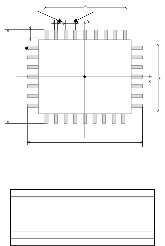
As the left/right and upper/lower leads of the QFP components are symmetrical, the
components can be expressed in one group. Also, the outer shape is determined based on
the lead tips. Therefore, the center of the QFP component is equal to the center of the outer
shape.
The lead length, the lead pitch, the lead width are the same in each direction and only the
number of the leads in N/S and E/W direction may be different.
For these reasons, it is possible to define the component shape as long as the following
information is available.
- Body size X (xsize)
- Body size Y (ysize)
- Body size Z (zsize)
- Lead Number N (hnum)
- Lead Number E (vnum)
- Lead pitch (pitch)
- LeadWidth (width)
- ReflectLL. (length)
Figure 8
The following is the explanation of the above mentioned simple setting for QFP component.
In the QFP mode, the component data (shape parameters) is created automatically in the
machine by just setting the data indicated in Table 3.
Items to be set Set Value
Body Size X (mm) Xsize
Body Size Y (mm) ysize
Lead Number N hnum
Lead Number E vnum
Lead pitch (mm) pitch
Lead width (mm) width
Reflecting lead length (mm) length
Table 3
Number of the leads N
Body Size X
Number of the leads E
Reflect lead length
Body Size Y
Center of the component
Lead Pitch
Lead Width
S direction
N direction
E direction
W direction
15/178
IM-SMT-VSNDIC-0002-000
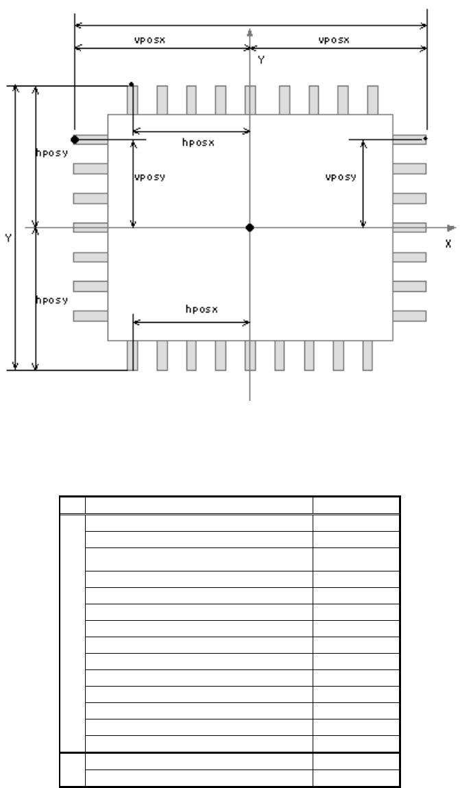
<Automatic settings>
The setting is calculated as follows (See
Figure 9
):
hposx = (hnum - 1) * pitch / 2
hposy = ysize / 2
vposx = xsize / 2
vposy = (vnum - 1) * pitch / 2
Figure 9
<< The result of the automatic setting for GFP recognition >>
Items to be set Set value
Alignment Group IC
Alignment Type QFP
Comp. Threshold -
Comp. Tolerance -
Search Area (mm) -
Body Size X (mm) xsize
Body Size Y (mm) ysize
Body Size Z (mm) zsize
Cntr. Offset X (mm) 0
Cntr. Offset Y (mm) 0
Cntr. Offset R (mm) 0
Ruler Width 3
Algorithm 0
Base Alignment 0
Vision Option 0
Vision Option 2 0
Body Size X (xsize)
Body Size Y (ysize)
Center of the component
S
E
W
N
16/178
IM-SMT-VSNDIC-0002-000
Items to be set Set value
Vision Option 3 0
Vision Option 4 0
Table 4
<<N direction data>>
Items to be set Set value
Lead group N 1
Ruler Offset N 3
Items to be set Set value Items to be set Set value
Lead Number 1N hnum Lead Number 2N 0
Reflect LL 1N (mm)
length Reflect LL 2N (mm) 0
Lead Width 1N (mm)
width Lead Width 2N (mm) 0
Lead Pitch 1N (mm)
pitch Lead Pitch 2N (mm) 0
Find Pos X 1N (mm) -hposx Find Pos X 2N (mm) 0
Find Pos Y 1N (mm) hposy Find Pos Y 2N (mm) 0
<<S direction data>>
Items to be set Set value
Lead group S 1
Ruler Offset S 3
Items to be set Set value Items to be set Set value
Lead Number 1S hnum Lead Number 2S 0
Reflect LL 1S (mm)
length Reflect LL 2S (mm) 0
Lead Width 1S (mm)
width Lead Width 2S (mm) 0
Lead Pitch 1S (mm)
pitch Lead Pitch 2S (mm) 0
Find Pos X 1S (mm)
- hposx Find Pos X 2S (mm) 0
Find Pos Y 1S (mm)
- hposy Find Pos Y 2S (mm) 0
<<E direction data>>
Items to be set Set value
Lead group E 1
Ruler Offset E 3
Items to be set Set value Items to be set Set value
Lead Number 1E vnum Lead Number 2E 0
Reflect LL 1E (mm)
length Reflect LL 2E (mm) 0
Lead Width 1E (mm)
width Lead Width 2E (mm) 0
Lead Pitch 1E (mm)
pitch Lead Pitch 2E (mm) 0
Find Pos X 1E (mm)
- vposx Find Pos X 2E (mm) 0
Find Pos Y 1E (mm)
vposy Find Pos Y 2E (mm) 0
<<W direction data>>
Items to be set Set value
Lead group W 1
Ruler Offset W 3