创建组件识别数据的方法.pdf - 第155页
155/178 IM-SMT-VSNDI C-0002 -000 2.12.4. Sp ecial Quad This is the recog nition m ode used for rectangular components. Squares c an also be recognized with this mode. << Items to be set for rec ognition of Sp Quads…
154/178
IM-SMT-VSNDIC-0002-000
Option 2: Min. Brightness Difference (If the value is 0, 50 is set)
If the difference of the average brightness of the detected circle is less than the
value specified here, it is determined to be an error.
Option 4: “Cut Inner /Outer Noise”, the priority to perform “Cut Inner /Outer Noise”
function and the object type are specified.
The detection conditions for direction check are set to 1N Lead Group.
- Lead Group 1N: 1
*The detecting conditions for direction check are set to 1N Lead Group
- Lead Number 1N: 0
- Reflect LL 1N: 0
- Lead width 1N: Diameter of detection circle (mm)
- Lead pitch 1N: 0
- Find Pos. X 1N: Detection circle center position X
- Find Pos. Y 1N : Detection circle center position Y
Based on the results obtained from the “Direction check”, add +90°, +180° or +270° to
the tilt of the component and set the values.
(2) Special 8: 2 Objects (Angle of Terminal)
Perform the same recognition method as that of Mark 2.
The average center-of-gravity of the two objects is determined to be the center of the
component, and the inclination is determined as the inclination of the straight lines which
configure the objects.
When the straight lines configure the shape of the lead, the angle may be obtained more
correctly compare to the recognition by Mark 2.
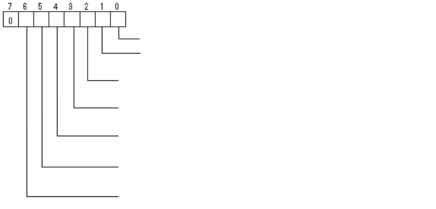
Bit position
Check Type: (0: Black, 1: White)
Check Direction: (0: (0°, 180°), 1: (0°, 90°, 180°, 270°)
Least-square method is always used when performing inclination detection.
(For all the sides)
Performs inclination detection with reference to the side in N direction.
(when the inclination is not obtained correctly.)
Performs inclination detection with reference to the side in S direction.
(when the inclination is n
ot obtained correctly.)
Performs inclination detection with reference to the side in W direction.
(when the inclination is not obtained correctly.)
Performs inclination detection with reference to the side in E direction.
(when the inclination is not obt
ained correctly.)
155/178
IM-SMT-VSNDIC-0002-000
2.12.4. Special Quad
This is the recognition mode used for rectangular components. Squares can also be
recognized with this mode.
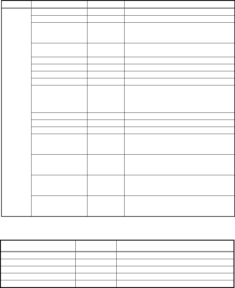
<< Items to be set for recognition of Sp Quads >>
Items to be set Set value Explanation
Alignment Group Special Sets the component category.
Alignment Type Sp. Quad Sets the component type.
Comp. Threshold
Sets the binarization level.
(If 0 is specified, the threshold is set
automatically.)
Comp. Tolerance
Specifies the shape tolerance as a
percentage.
Search Area (mm) Sets the range of the detection.
Body Size X (mm) Sets the size of the outer edge.
Body Size Y (mm) Sets the size of the outer edge.
Body Size Z (mm) Sets the size of the outer edge.
Surface Type
Selects from reflect and non-reflect.
Selects reflect when the component
appears to be white and selects
non-reflect when it does not.
Cut Outer Noise Select from 0 through 7.
Cut Inner Noise Select from 0 through 7.
Noise Cut Order Selects from “Inner” or ”Outer”.
Lead Number N
When not performing line detection in
the N direction, this sets the value
other than 0.
Lead Number S
When not performing line detection in
the S direction, this sets the value other
than 0.
Lead Number E
When not performing line detection in
the E direction, this sets the value other
than 0.
Common
Data
Lead Number W
When not performing line detection in
the W direction, this sets the value
other than 0.
Table 102
[Recognition check items]
Items Yes / No Notes
Body Size Yes
Lead pitch No
Lead width No
Lead length No
Lead position No
Table 103
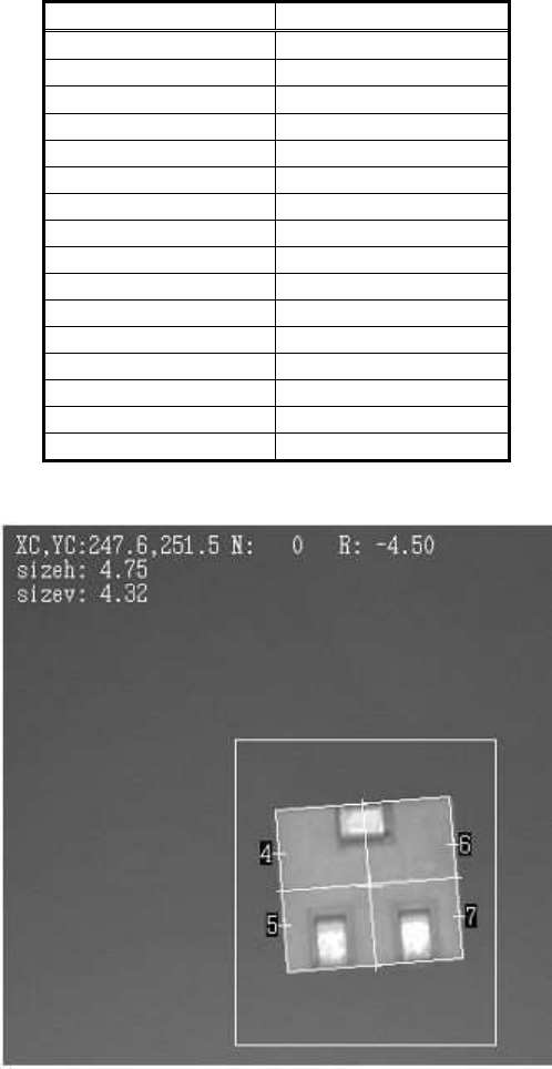
The following is the actual definition data of the component (semi-fixed resistor) and the
recognition result.
156/178
IM-SMT-VSNDIC-0002-000
Items to be set Set value
Alignment Group Special
Alignment Type Sp. Quad
Comp. Threshold 0
Comp. Tolerance 30
Search Area (mm) 15.0
Body Size X (mm) 22.0
Body Size Y (mm) 22.0
Body Size Z (mm) 0.5
Surface Type Reflect
Cut Outer Noise 0
Cut Inner Noise 0
Noise Cut Order --
Lead Number N 1
Lead Number S 1
Lead Number E 0
Lead Number W 0
Table 104
Figure 126
As the component has leads in the N/S direction, the value “1” is set to “Lead Number N/S” in
order to avoid line detection in the N/S direction.
As a result, recognition is carried out only in the right/left (E/W) direction.
The following shows the recognition results of the actual component (trimmer capacitor).
Recognition was performed only in the left/right (W/E) direction for these components.