创建组件识别数据的方法.pdf - 第71页
71/178 IM-SMT-VSNDI C-0002 -000 Figure 55 [Recognition check items ] Items Y es / No Notes Body Size No Lead pitch Y es The pitch in th e direction with one lead is not check ed. Lead width May exist Checks only when the…
70/178
IM-SMT-VSNDIC-0002-000
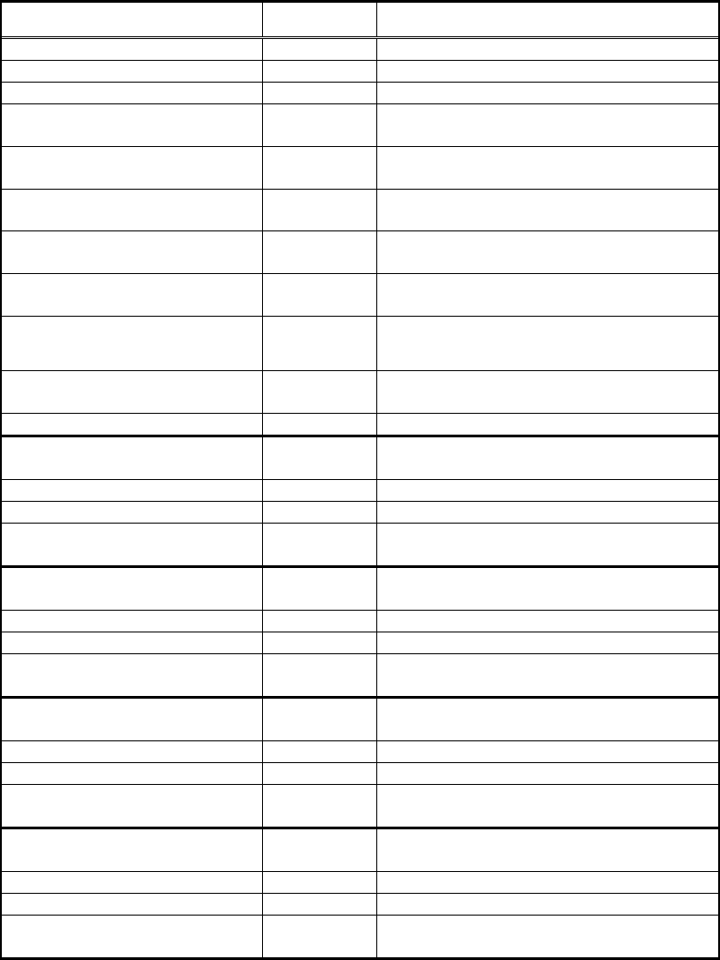
Items to be set Set value Explanation
Body Size X (mm) Sets the size of the outer edge.
Body Size Y (mm) Sets the size of the outer edge.
Body Size Z (mm) Sets the size of the outer edge.
Cntr. Offset X (mm)
Sets the offset amount in the X direction
from the center position.
Cntr. Offset Y (mm)
Sets the offset amount in the Y direction
from the center position.
Cntr. Offset R (mm)
Sets the offset amount of the angle of
rotation.
Ruler Offset N
Sets the offset amount for the detection
line in the N direction.
Ruler Offset S
Sets the offset amount for the detection
line in the S direction.
Ruler Offset E
Sets the offset amount for the detection
line in the E direction.
Ruler Offset W
Sets the offset amount for the detection
line in the W direction.
Ruler Width
Lead Number N
Sets the number of leads in the N
direction.
Lead Pitch N (mm) Sets the lead pitch in the N direction.
Lead Width N (mm) Sets the lead width in the N direction.
Reflect LL. N (mm)
Sets the lead length on the image in the
N direction.
Lead Number S
Sets the number of leads in the S
direction.
Lead Pitch S (mm) Sets the lead pitch in the S direction.
Lead Width S (mm) Sets the lead width in the S direction.
Reflect LL. S (mm)
Sets the lead length on the image in the
S direction.
Lead Number E
Sets the number of leads in the E
direction.
Lead Pitch E (mm) Sets the lead pitch in the E direction.
Lead Width E (mm) Sets the lead width in the E direction.
Reflect LL. E (mm)
Sets the lead length on the image in the
E direction.
Lead Number W
Sets the number of leads in the W
direction.
Lead Pitch W (mm) Sets the lead pitch in the W direction.
Lead Width W (mm) Sets the lead width in the W direction.
Reflect LL. W (mm)
Sets the lead length on the image in the
W direction.
Table 47
This mode can be used for recognition of not only four directions but also one direction, two
directions and three directions.
The data should be set for only the necessary direction(s), and data for directions that are
not necessary should be set to 0.
Leads in the N/S direction must be symmetrical on the left and right sides, and leads in
the W/E direction must be symmetrical on the upper and lower sides. This is because the
reference lead position is determined from the center of the outer edge, based on the Lead
Number and the Lead Pitch.
71/178
IM-SMT-VSNDIC-0002-000
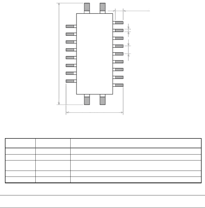
Figure 55
[Recognition check items]
Items Yes / No Notes
Body Size No
Lead pitch Yes The pitch in the direction with one lead is not checked.
Lead width
May exist
Checks only when the lead width is more than 1.0mm.
(Note 1)
Reflect LL No
Find Pos No
Table 48
Note:
“Lead width” check function may not be available for the old software versions.
Lead length
Lead width
Lead pitch
Body Size X
Body Size Y
72/178
IM-SMT-VSNDIC-0002-000
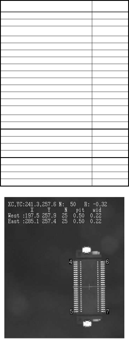
The following is the actual example of the setting and the recognition result.
<< Items to be set for 2-direction connectors>>
Items to be set Set value
Alignment Group Connector
Alignment Type Con-NSEW
Comp. Threshold 50
Comp. Tolerance 30
Search Area (mm) 4.0
Body Size X (mm) 8.0
Body Size Y (mm) 14.0
Body Size Z (mm) 7.0
Cntr. Offset X (mm) 0.0
Cntr. Offset Y (mm) 0.0
Cntr. Offset R (mm) 0.0
Ruler Offset N 0
Ruler Offset S 0
Ruler Offset E 5
Ruler Offset W 5
Ruler Width 3
Lead Number E 25
Lead Pitch E (mm) 0.5
Lead Width E (mm) 0.2
Reflect LL. E (mm) 0.8
Lead Number W 25
Lead Pitch W (mm) 0.5
Lead Width W (mm) 0.2
Reflect LL. W (mm) 0.8
Table 49
Figure 56