创建组件识别数据的方法.pdf - 第58页
58/178 IM-SMT-VSNDI C-0002 -000 Set the direction determination data to the second Lead Group of the di rection set in Option 2. - Num ber of the leads * “Angle correc tion” m ode needs to be custom ordered. - Lead pitch…
57/178
IM-SMT-VSNDIC-0002-000
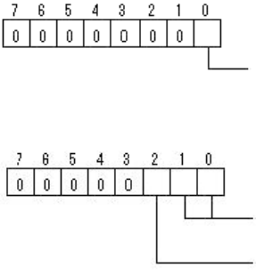
Option 3: Recognition Flag
Option 4: Corner detection filter:
2) Special 2: NS Base Search
In this mode, SOJ recognition is performed by first using the leads in the N/S
direction, then based on the data, the recognition of W/E direction is performed.
Option 1: Lead detection flag (same as Special 1)
Option 3
: Recognition Flag (same as Special 1)
3) Special 3: WE Base Search
In this mode, SOJ recognition is performed by first using the leads in the W/E
direction, then based on the data, the recognition of N/S direction is performed.
Option 1
: Lead detection flag (same as Special 1)
Option 3: Recognition Flag (same as Special 1)
4) Special 4: Check Direction
It compares the average brightness of the specified circular region and the
other circular region located 180 degrees opposed (diagonal) from the
specified circular region in order to identify the direction.
Option 1: Lead Detection Flag (same as Special 1)
Option 2: Direction of mark: (0:N, 1:S, 2:W, 3:E)
Option 3: Recognition flag (same as Special 1)
Option 4: Corner detection filter (same as Special1)
Bit position
Excessive Lead Check (0:Non, 1:Exist)
(It checks whether the extra leads exist outside of pitch 1)
Bit position
Lead Search Filter: (0:None, 1:Once, 2: Twice)
(Noise
elimination
filter is used when detecting the corner.)
Right Angle Fitting: 0:None, 1:Exist
(It checks the perpendicularity of the candidate
adjacent sides when extracting the corner.)
58/178
IM-SMT-VSNDIC-0002-000
Set the direction determination data to the second Lead Group of the direction set in Option
2.
- Number of the leads
* “Angle correction” mode needs to be custom ordered.
- Lead pitch: Min. Brightness Difference (If the value is 0, 50 is set)
If the difference of the average brightness of the detected circle is less than
the value specified here, it is determined to be an error.
- Lead width: The diameter of the detecting circle (mm)
- Reflect LL: 0
- Find Pos X: The center position X of the detecting circle
- Find Pos Y: The center position Y of the detecting circle
<< Items to be set for PLCC Special recognition>>
Items to be set Set value Explanation
Alignment Group Special Sets the component category.
Alignment Type Special Sets the component type.
Comp. Threshold
Sets the detection level difference for
lead detection
. (See “Appendix 2.
Detection level differences used to detect
leads (threshold value)”.)
Comp. Tolerance
Specifies the tolerance of the lead
pitch as a percentage.
Search Area (mm) Sets the range of the detection.
Body Size X (mm) Sets the size of the outer edge.
Body Size Y (mm) Sets the size of the outer edge.
Body Size Z (mm) Sets the size of the outer edge.
Cntr. Offset X (mm)
Sets the offset amount in the X
direction from the center position.
Cntr. Offset Y (mm)
Sets the offset amount in the Y
direction from the center position.
Cntr. Offset R (mm)
Sets the offset amount of the angle of
rotation.
Ruler Width
Algorithm Special 1-4
Selects the recognition algorithm
when using a special algorithm.
Base Alignment PLCC
Selects the basic component type
when using a special algorithm.
Vision Option 1 Sets option parameter 1.
Vision Option 2 Sets option parameter 2.
Vision Option 3 Sets option parameter 3.
Common
Data
Vision Option 4 Sets option parameter 4.
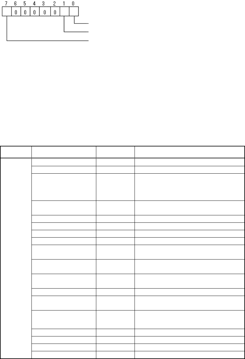
Bit position
Check Direction ( 0: 2 angle,1: 4 angle)
Check Type (0:Black, 1:White)
Judgment method ( 0: Error, 1: Angle correction)

59/178
IM-SMT-VSNDIC-0002-000
Items to be set
Set
value
Explanation
Lead Group N 1
Specifies the number for the
Lead Group in the N direction.
Common
Ruler Offset N
Sets the offset amount of the
detection line in the N
direction.
Lead Number: 1N
Sets the number of leads in
the N direction.
Reflect LL.: 1N (mm)
Sets the lead length on the
image in the N direction.
Lead Width: 1N (mm)
Sets the width of the lead in
the N direction.
Lead Pitch: 1N (mm)
Sets the pitch in the N
direction.
Find Pos X: 1N (mm)
Sets the reference position X
in the N direction.
N
Direction
Group 1
Find Pos Y: 1N (mm)
Sets the reference position Y
in the N direction.
Lead Group S 1
Specifies the number for the
Lead Group in the S
direction.
Common
Ruler Offset S
Sets the offset amount of the
detection line in the S
direction.
Lead Number: 1S
Sets the number of leads in
the S direction.
Reflect LL.: 1S (mm)
Sets the lead length on the
image in the S direction.
Lead Width: 1S (mm)
Sets the width of the lead in
the S direction.
Lead Pitch: 1S (mm)
Sets the pitch in the S
direction.
Find Pos X: 1S (mm)
Sets the reference position X
in the S direction.
S
Direction
Group 1
Find Pos Y: 1S (mm)
Sets the reference position Y
in the S direction.
Lead Group E 1
Specifies the number for the
Lead Group in the E direction.
Common
Ruler Offset E
Sets the offset amount of the
detection line in the E
direction.
Lead Number: 1E
Sets the number of lead in the
E direction.
Reflect LL.: 1E (mm)
Sets the lead length on the
image in the E direction.
Lead Width: 1E (mm)
Sets the width of the leads in
the E direction.
Lead Pitch: 1E (mm)
Sets the pitch in the E
direction.
Find Pos X: 1E (mm)
Sets the reference position X
in the E direction.
E
Direction
Group 1
Find Pos Y: 1E (mm)
Sets the reference position Y
in the E direction.