创建组件识别数据的方法.pdf - 第40页
40/178 IM-SMT-VSNDI C-0002 -000 T able 26 shows the recogn ition results obtained with a s ingle camera. <Items to be set f or SOPs > Items to be set Set value Alignment Group S pecial Alignment T ype S peci al Com…
39/178
IM-SMT-VSNDIC-0002-000
Items to be set
Set
value
Explanation
Lead Width: 1W
(mm)
Sets the width of the lead in the
W direction.
Lead Pitch: 1W
(mm)
Sets the pitch in the W direction.
Find Pos X: 1W
(mm)
Sets the reference position X of
the lead in the W direction.
Find Pos Y: 1W
(mm)
Sets the reference position Y of
the lead in the W direction.
Table 25
Note:
The parameters other than those shown in
Table 25
are not used, and should be set to 0.
1) Special 1: This is the same recognition method as SOJ recognition. (SOJ recognition
should be used in order to run this mode.)
This mode improves the recognition rate by checking the positional relations
between the leads and extracting the combination best fits the component
definition when detecting the end leads.
2) Special 2: Not supported
3) Special 3: Not supported
4) Special 4: Not supported
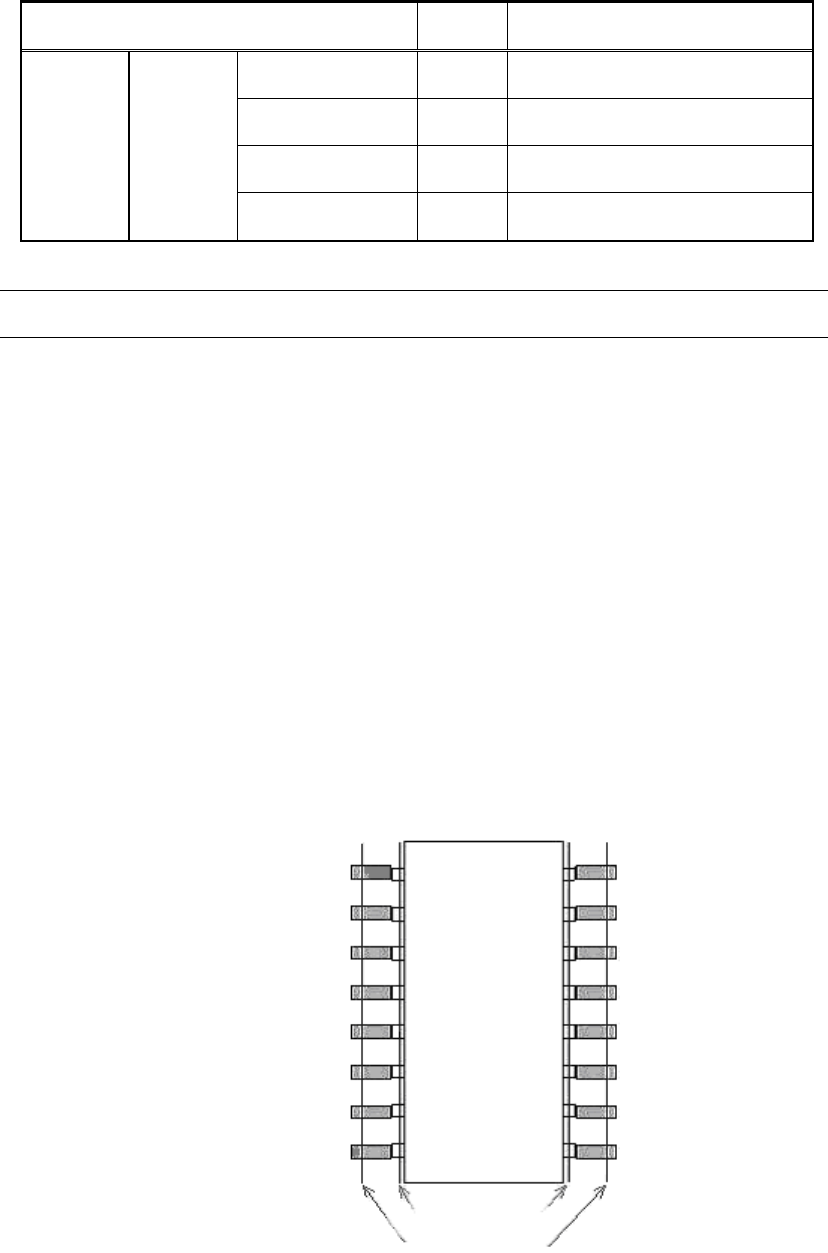
5) Special 5: SOP upside-down judgment (LeadPitch)
This compares the lead pitches at the tip and root of the lead in order to check
the reversed component.
In order to set the inner detection line, the lead length is set to a length slightly
longer than the normal value. (This should be set so that the detection line
extends to the lead section.) This recognition method is available only when
using a single camera.
When using a multi-camera, it is impossible to perform recognition of the
leads aligned in the E/W direction.
If this method is being used, the leads should be aligned in N/S direction
before carrying out the recognition.
Figure 31
Root detection line
Tip detection line
40/178
IM-SMT-VSNDIC-0002-000
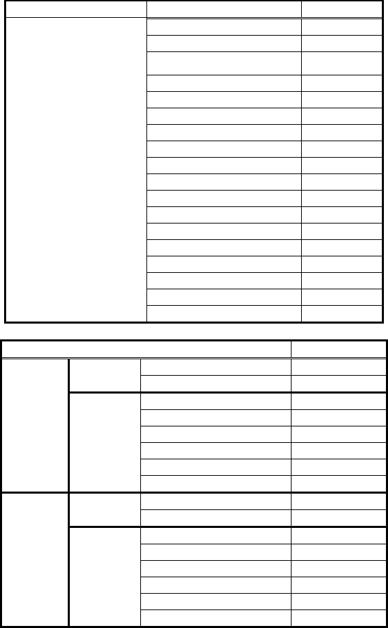
Table 26 shows the recognition results obtained with a single camera.
<Items to be set for SOPs>
Items to be set Set value
Alignment Group Special
Alignment Type Special
Comp. Threshold 50
Comp. Tolerance 30
Search Area (mm) 3.0
Body Size X (mm) 6.4
Body Size Y (mm) 10.15
Body Size Z (mm) 2.1
Cntr. Offset X (mm) 0.0
Cntr. Offset Y (mm) 0.0
Cntr. Offset R (mm) 0.0
Ruler Width 3
Algorithm Special 5
Base Alignment SOP
Vision Option 1 0
Vision Option 2 0
Vision Option 3 0
Common
Data
Vision Option 4 0
Items to be set Set value
Lead Group E 1
Common
Ruler Offset E 4
Lead Number: 1E 8
Reflect LL.: 1E (mm) 1.0
Lead Width: 1E (mm) 0.45
Lead Pitch: 1E (mm) 1.27
Find Pos X: 1E (mm) 3.2
E
Direction
Group
1
Find Pos Y: 1E (mm) 4.445
Lead Group W 1
Common
Ruler Offset W 4
Lead Number: 1W 8
Reflect LL.: 1W (mm) 1.0
Lead Width: 1W (mm)
0.45
Lead Pitch: 1W (mm) 1.27
Find Pos X: 1W (mm) -3.2
W
Direction
Group
1
Find Pos Y: 1W (mm) 4.445
Table 26
41/178
IM-SMT-VSNDIC-0002-000
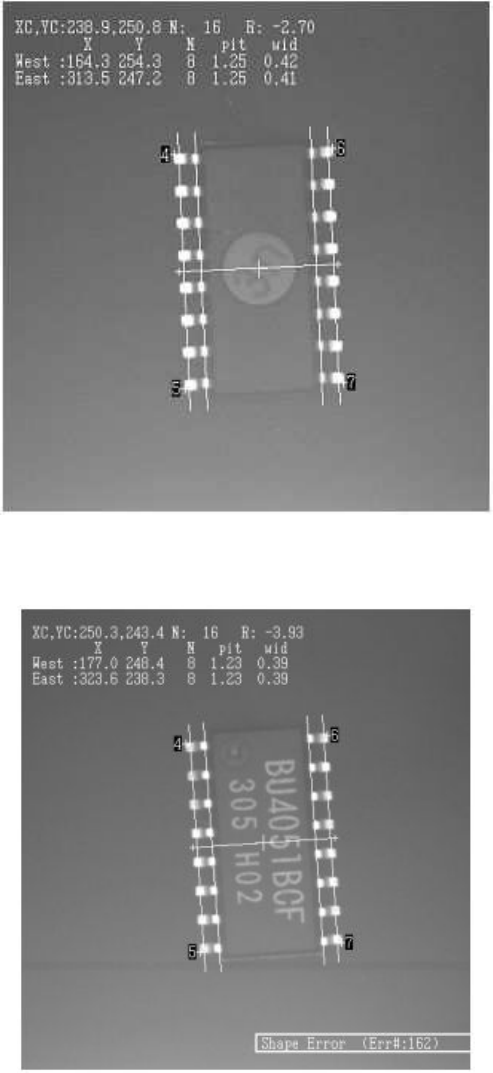
<When the component is correctly positioned >
Figure 32
<When a reversed component is detected>
Figure 33
6) Special 6: Check the bending of the whole leads of SOP components
This mode checks to see if all of the leads of an SOP are bent between the tips
and the roots of the leads. The recognition mode is the same as that of Special
1.
Option 1: Bending angle tolerance value