创建组件识别数据的方法.pdf - 第101页
101/178 IM-SMT-VSNDI C-0002 -000 Items to be set Set value Explanation S tartPos X W (mm ) Sets t he bump center position X of the starting position in the W direction. S tartPos Y W (mm) Sets the bum p center position Y…

100/178
IM-SMT-VSNDIC-0002-000
2.10.4 Flip-chip recognition
<<Items to be set for Flip-ships>>
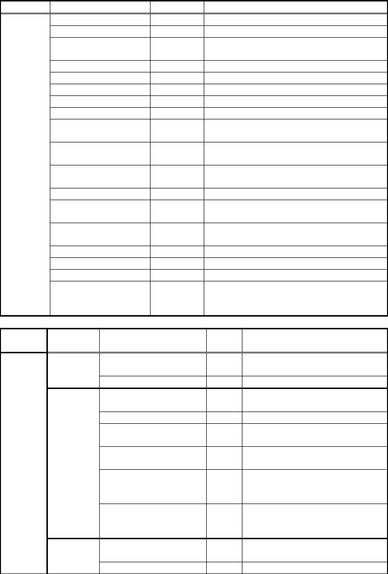
Items to be set Set value
Explanation
Alignment Group Ball Sets the component category.
Alignment Type Flip Chip
Sets the component type.
Comp. Threshold
Sets the binarization level. (If 0, the binarization
level is set automatically.)
Comp. Tolerance Specifies the tolerance as a percentage.
Search Area (mm) Sets the range of the detection.
Body Size X (mm) Sets the size of the outer edge.
Body Size Y (mm) Sets the size of the outer edge.
Body Size Z (mm) Sets the size of the outer edge.
Bump Number N
Sets the number of BGA ball rows in the N
direction.
Diameter N (mm)
Sets the diameter of the solder balls in the N
direction.
StartPos X N (mm)
Sets the bump center position X of the starting
position in the N direction.
StartPos Y N (mm)
Sets the bump center position Y of the starting
position in the N direction.
End Pos X N (mm)
Sets the bump center position X of the ending
position in the N direction.
End Pos Y N (mm)
Sets the bump center position Y of the ending
position in the N direction.
Bump Number S
Sets the number of BGA ball rows in the S
direction.
Diameter S (mm)
Sets the diameter of the solder balls in the S
direction.
StartPos X S (mm)
Sets the bump center position X of the starting
position in the S direction.
StartPos Y S (mm)
Sets the bump center position Y of the starting
position in the S direction.
End Pos X S (mm)
Sets the bump center position X of the ending
position in the S direction.
End Pos Y S (mm)
Sets the bump center position Y of the ending
position in the S direction.
Bump Number E
Sets the number of BGA ball rows in the E
direction.
Diameter E (mm)
Sets the diameter of the solder balls in the E
direction.
StartPos X E (mm)
Sets the bump center position X of the starting
position in the E direction.
StartPos Y E (mm)
Sets the bump center position Y of the starting
position in the E direction.
End Pos X E (mm)
Sets the bump center position X of the ending
position in the E direction.
End Pos Y E (mm)
Sets the bump center position Y of the ending
position in the E direction.
Bump Number W
Sets the number of BGA ball rows in the W
direction.
Diameter W (mm)
Sets the diameter of the solder balls in the W
direction.
101/178
IM-SMT-VSNDIC-0002-000
Items to be set Set value
Explanation
StartPos X W (mm)
Sets the bump center position X of the starting
position in the W direction.
StartPos Y W (mm)
Sets the bump center position Y of the starting
position in the W direction.
End Pos X W (mm)
Sets the bump center position X of the ending
position in the W direction.
End Pos Y W (mm)
Sets the bump center position Y of the ending
position in the W direction.
Table 70
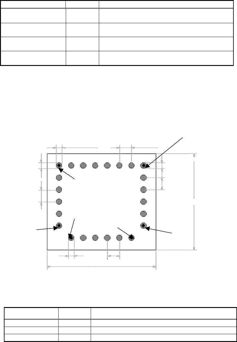
This is the recognition mode used for flip-chips such as shown in Figure 75.
Only the balls on the outer periphery are recognized. The centers of the balls on each side
where recognition is to start and end are specified. It is possible to specify the same ball for
both the horizontal and vertical directions.(In Figure 75, the starting points in the N and W
directions share the same point, and the ending points in the N direction and the ending point
in the E direction share the same point.)
Figure 75
[Recognition check items]
Items Yes / No
Notes
Body Size No
Ball pitch No
Number of balls Yes
Table 71
Dia
meter N
Diameter W
Diameter E
Diameter S
Pitch N
Pitch E
Pitch S
Pitch W
Body Size Y
Body Size X
Start Pos N/W
Start Pos S
End Pos N
Start Pos E
End Pos E
End Pos S
End Pos W
102/178
IM-SMT-VSNDIC-0002-000
2.10.5. Flip-chip recognition: Special 1
<< Items to be set for Flip-chip Special 1>>
Items to be set Set value
Explanation
Alignment Group Special Sets the component category.
Alignment Type Special Sets the component type.
Comp. Threshold
Sets the binarization level. (If 0, the
binarization level is set automatically.)
Comp. Tolerance Specifies the tolerance as a percentage.
Search Area (mm) Sets the range of the detection.
Body Size X (mm) Sets the size of the outer edge.
Body Size Y (mm) Sets the size of the outer edge.
Body Size Z (mm) Sets the size of the outer edge.
Cntr. Offset X (mm)
Sets the offset amount in the X direction
from the center position.
Cntr. Offset Y (mm)
Sets the offset amount in the Y direction
from the center position.
Cntr. Offset R (mm)
Sets the offset amount of the angle of
rotation.
Ruler Width 0
Algorithm Special 1
Selects the recognition algorithm when
using a special algorithm.
Base Alignment Flip Chip
Selects the basic component type when
using a special algorithm.
Vision Option 1
Note *2
Sets option parameter 1.
Vision Option 2 0
Vision Option 3 0
Common
Data
Vision Option 4
Note *1
Specifies the noise cut for inside and
outside of the component, the order of
execution and the object type.
Items to be set
Set
value
Explanation
Lead Group N
Sets the number of the Lead
Group (1 or 2).
Common
Ruler Offset N 0
Lead Number: 1N
Sets the number of balls of
Group 1 in the N direction.
Reflect LL.: 1N (mm) 0.0
Lead Width: 1N (mm)
Note*4
Sets the diameter of the balls of
Group 1 in the N direction.
Lead Pitch: 1N (mm)
Sets the ball pitch of Group 1 in
the N direction.
Find Pos X: 1N (mm)
Note*5
Sets the reference position X
for the ball of Group 1 in the N
direction.
Group
1
Find Pos Y: 1N (mm)
Note*5
Sets the reference position Y
for the ball of Group 1 in the N
direction.
Lead Number: 2N
Sets the number of balls of
Group 2 in the N direction.
N
direction
Group
2
Reflect LL.: 2N (mm) 0.0