创建组件识别数据的方法.pdf - 第119页
119/178 IM-SMT-VSNDI C-0002 -000 “Align size X, Y” are used to check the component si ze. The size of the outer edge is set to “Body Size” and the component size on the image is set to “Align size”. Figure 93 [Recognitio…
118/178
IM-SMT-VSNDIC-0002-000
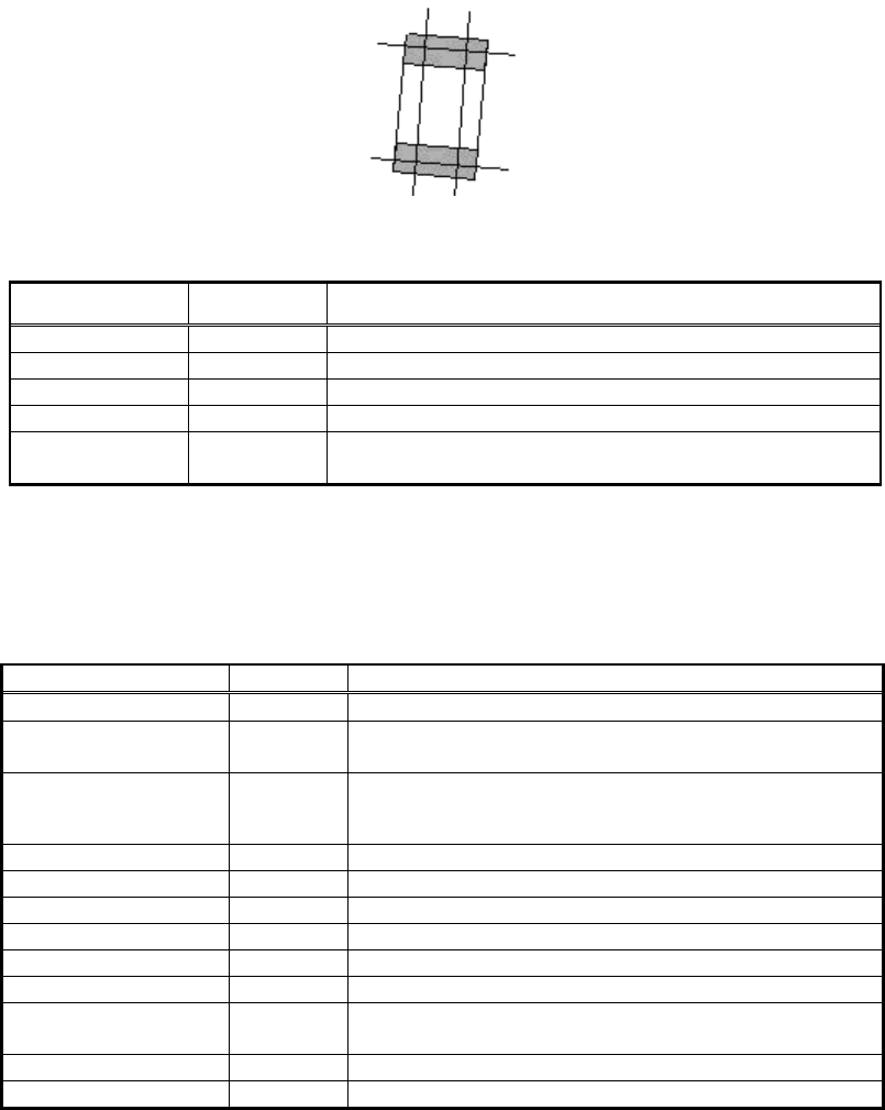
Not only the size of the outer edge, but also the lead width can be set. This mode is used
when the size of the outer edge and the lead width are different.
In addition to the outer edge sizes, the amount of offset from the center position can be set.
This makes it possible to offset the center of mounting position.
Figure 92
[Recognition check items]
Items Yes / No Notes
Body Size May exist Only Body Size Y is checked
Lead pitch No
Lead width Yes
Lead length No
Lead position Yes
Checks whether the center of the detected lead tip is in
the range of Body Size Y x tolerance.
Table 85
2.11.6. Small Chip
<<Items to be set for Small chips>>
Items to be set Set value
Explanation
Alignment Group Chip Sets the component category
Alignment Type
Small
Chip
Sets the component type
Comp. Threshold
Sets the detection level difference for lead detection
(See “Appendix 2. Detection level differences used to
detect leads (threshold value)”.)
Comp. Tolerance
Sets the shape tolerance as a percentage
Search Area (mm)
Sets the range for detection
Body Size X (mm)
Sets the outer edge size
Body Size Y (mm)
Sets the outer edge size
Body Size Z (mm)
Sets the outer edge size
Ruler Offset
Sets the offset amount for the detection line
Reflct LL
Sets the length of the electrode. (If 0.2mm is set, it is
the same setting as Standard chip.)
Align size X (mm)
Sets the size X recognized on the image.
Align size Y (mm)
Sets the size Y recognized on the image.
Table 86
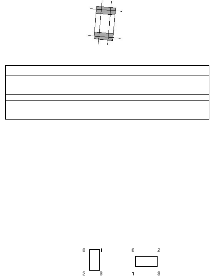
This mode is used for the components smaller than 1005.
These components look smaller on the image compare to the actual size, which affects the
recognition. When recognizing these small components, the difference between the
recognized size and the actual component size become large, and the effect on recognition
becomes large accordingly. This mode is used to deal with the symptom.
119/178
IM-SMT-VSNDIC-0002-000
“Align size X,Y” are used to check the component size.
The size of the outer edge is set to “Body Size” and the component size on the image is set to
“Align size”.
Figure 93
[Recognition check items]
Items Yes / No
Notes
Body Size Yes
Lead pitch No
Lead width Yes
Lead length
Lead position No
Nozzle check
Yes
“Lead Brightness” check.
Note *1
“Symmetry” check (Only when the threshold is set to 0.)
Table 87
Note *1:
The “Lead Brightness” function checks if the brightness of the electrode section of the chip is
smaller than the specified value. If it is smaller, it is detected to be an error.
2.11.6. Special recognition of chip components (standard chips, MELF chips,
special chips)
There are a number of special recognition algorithms available for the Standard Chip, MELF
Chip, and Special Chip Recognition modes.
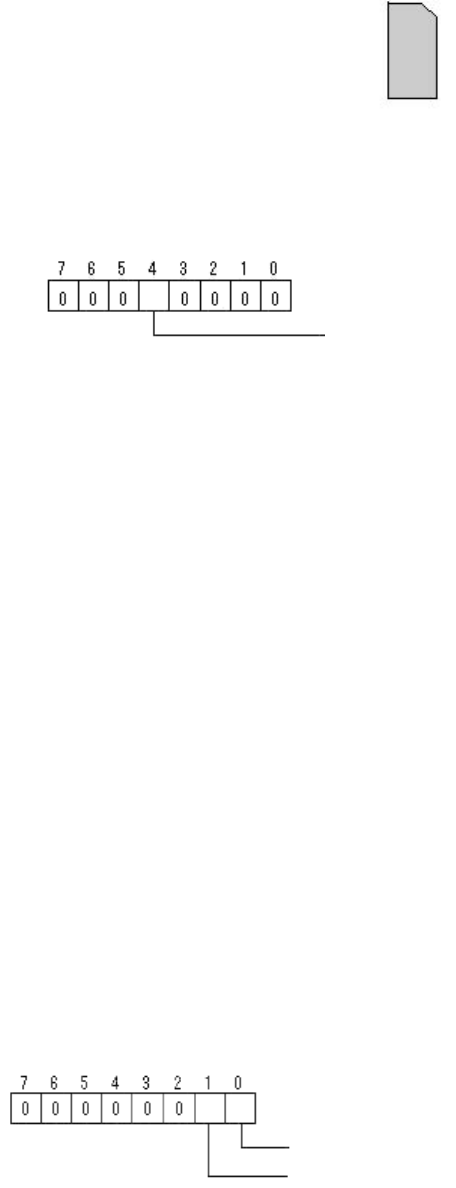
(1) Special 1: Chamfer Lead
Option 1: This is used to specify the direction of the component whose leads are partly
missing. (Sets the numbers as shown in Figure 94.)
Figure 94
For instance, when performing recognition on the component placed vertically like shown in
Figure 95, 1 is specified.
Vertically placed
Horizontally placed
120/178
IM-SMT-VSNDIC-0002-000
Figure 95
(2) Special 2: Check Lead Brightness
Option 1: Recognition Flag
Option 2: Comp. Intensity (0-255)
Option 3: Check method
0: Lead Brightness
This checks to see if the brightness of the electrode section of the chip is
smaller (darker) than the specified value. If it is smaller, it is determined to be
an error.
1: Lead Brightness + Symmetry
(This mode is used if the chip is a standard chip and the threshold value is 0.)
Please refer to “2.11.1. Standard chips” for “Symmetry”.
2: Lead Brightness + Difference
In “Difference” mode, when the upper and lower (or left and right) brightness
ratio exceeds a certain value (less than 0.7 or more than 1.5), it is determined
to be an error.
Option 4: Trapezoid Tolerance (0-255)%
Even though the lead width on one side is out of the tolerance range, if the
lead width on the other side is within the tolerance and the degree of
trapezoid (the ratio between the widest and narrowest lead width) is within the
trapezoidal tolerance, it is determined to be satisfactory.
(3) Special 3: Check Direction
The direction of the component is determined by the brightness of the specified circular
region. (*This needs to be custom-ordered.)
Option 1: Recognition Flag
Option 2: Min. Brightness Difference (If 0, 50 will be set)
If the difference in the average brightness of the detection circle checked for
direction determination is smaller than the value, it is determined to be an
error.
Bit position
Bit position
Check Type (0:Black, 1: White)
Check Direction (0:2
angle, 1: 4 angle)
Check Many Adsorption
(0: None, 1: Exist)