创建组件识别数据的方法.pdf - 第87页
87/178 IM-SMT-VSNDI C-0002 -000 Items to be set Set value Base Alignm ent S pecial Vision Option 1 0 Vision Option 2 0 Vision Option 3 0 Vision Option 4 0 Lead Group N 1 Comm on Ruler Offset N 3 Lead Num ber: 1N 1 Reflec…
86/178
IM-SMT-VSNDIC-0002-000
Items to be set Set value
Lead Pitch E (mm) 0.5
Lead Width E (mm) 0.2
Reflect LL. E (mm) 0.5
Lead Number W 60
Lead Pitch W (mm) 0.5
Lead Width W (mm) 0.2
Reflect LL. W (mm) 0.5
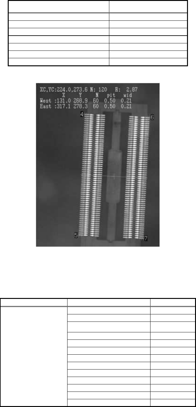
Table 57
Figure 65
The following is the actual example of the setting and recognition results of the components
on which some of the leads on the right and left sides are missing.
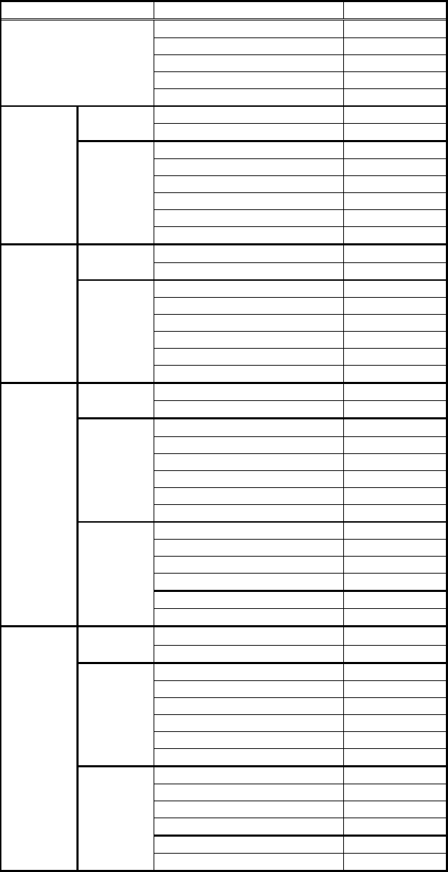
<<Items to be set for Special 1 connector>>
Items to be set Set value
Alignment Group Special
Alignment Type Special
Comp. Threshold 50
Comp. Tolerance 30
Search Area (mm) 3.0
Body Size X (mm) 3.0
Body Size Y (mm) 13.0
Body Size Z (mm) 3.0
Cntr. Offset X (mm) 0.0
Cntr. Offset Y (mm) 0.0
Cntr. Offset R (mm) 0.0
Ruler Width 3
Common
Data
Algorithm Special 1
87/178
IM-SMT-VSNDIC-0002-000
Items to be set Set value
Base Alignment Special
Vision Option 1 0
Vision Option 2 0
Vision Option 3 0
Vision Option 4 0
Lead Group N 1
Common
Ruler Offset N 3
Lead Number: 1N 1
Reflect LL.: 1N (mm) 1.0
Lead Width: 1N (mm) 0.9
Lead Pitch: 1N (mm) 0.0
Find Pos X: 1N (mm) 0.0
N
direction
Group 1
Find Pos Y: 1N (mm) 6.8
Lead Group S 1
Common
Ruler Offset S 3
Lead Number: 1S 1
Reflect LL.: 1S (mm) 1.0
Lead Width: 1S (mm) 0.9
Lead Pitch: 1S (mm) 0.0
Find Pos X: 1S (mm) 0.0
S
direction
Group 1
Find Pos Y: 1S(mm) -6.8
Lead Group E 2
Common
Ruler Offset E 3
Lead Number: 1E 2
Reflect LL.: 1E (mm) 0.8
Lead Width: 1E (mm) 0.6
Lead Pitch: 1E (mm) 2.0
Find Pos X: 1E (mm) 4.0
Group 1
Find Pos Y: 1E(mm) 3.0
Lead Number: 2E 1
Reflect LL.: 2E(mm) 0.8
Lead Width: 2Emm) 0.6
Lead Pitch: 2E(mm) 0.0
Find Pos X: 2E (mm) 4.8
E
direction
Group 2
Find Pos Y: 2E(mm) -3.0
Lead Group W
2
Common
Ruler Offset W 3
Lead Number: 1W 2
Reflect LL.: 1W (mm) 0.8
Lead Width: 1W (mm) 0.6
Lead Pitch: 1W (mm) 2.0
Find Pos X: 1W (mm) -0.4
Group 1
Find Pos Y: 1W(mm) 3.0
Lead Number: 2W 8
Reflect LL.: 2W(mm) 0.5
Lead Width: 2Wmm) 0.2
Lead Pitch: 2W(mm) 2.0
Find Pos X: 2W(mm) -4.0
W
direction
Group 2
Find Pos Y: 2Wmm) -3.0
Table 58
88/178
IM-SMT-VSNDIC-0002-000
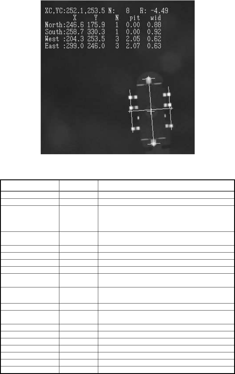
Figure 66
2.9.4. Odd-shape connectors
Items to be set Set value Explanation
Alignment Group Connector Sets the component category.
Alignment Type Odd. Con Sets the component type.
Comp. Threshold
Sets the detection level difference for lead
detection
.
(See “Appendix 2. Detection level differences used to
detect leads (threshold value)”.)
Comp. Tolerance
Specifies the tolerance of the lead pitch as a
percentage.
Search Area (mm) Sets the range of the detection.
Body Size X (mm) Sets the size of the outer edge.
Body Size Y (mm) Sets the size of the outer edge.
Body Size Z (mm) Sets the size of the outer edge.
Cntr. Offset X (mm)
Sets the offset amount in the X direction from the
center position.
Cntr. Offset Y (mm)
Sets the offset amount in the Y direction from the
center position.
Cntr. Offset R (mm)
Sets the offset amount of the angle of rotation.
Ruler Offset E
Sets the offset amount for the detection line in the
E direction.
Ruler Width
Lead Number E Sets the number of leads. (The gaps are included.)
Reflect LL. (mm) Sets the lead length on the image.
Lead Width (mm) Sets the lead width.
Lead Pitch (mm) Sets the lead pitch.
Off Lead Start E Sets the start position of the leads gap.
Off Lead End E Sets the end position of the leads gap.
Table 59