创建组件识别数据的方法.pdf - 第77页
77/178 IM-SMT-VSNDI C-0002 -000 Figure 60 <<Items to be set for Special 1 con nectors >> Items to be set Set value Alignment Group S pecial Alignment T ype S pecial Comp. Threshold 50 Comp. T olerance 30 Sear…
76/178
IM-SMT-VSNDIC-0002-000
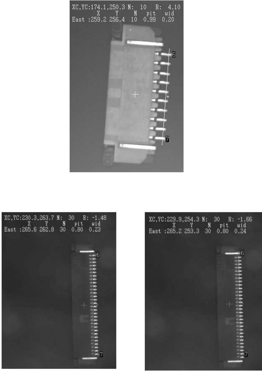
Figure 58
As described above, sometimes “Special 1” mode does not provide stable recognition.
When the leads for securing the connector are located close to the targeted leads, detection
error may occur as shown in Figure 59.
Figure 59
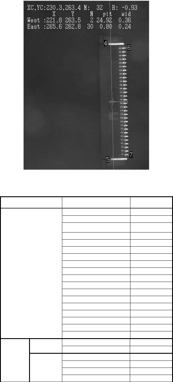
In this case, stable recognition can be performed by including leads used to secure
connectors as the target in the recognition process as shown in
Figure 60.
77/178
IM-SMT-VSNDIC-0002-000
Figure 60
<<Items to be set for Special 1 connectors>>
Items to be set Set value
Alignment Group Special
Alignment Type Special
Comp. Threshold 50
Comp. Tolerance 30
Search Area (mm) 5.0
Body Size X (mm) 7.0
Body Size Y (mm) 15.0
Body Size Z (mm) 2.0
Cntr. Offset X (mm) 0.0
Cntr. Offset Y (mm) 0.0
Cntr. Offset R (mm) 0.0
Ruler Width 3
Algorithm Special 1
Base Alignment Special
Vision Option 1 0
Vision Option 2 0
Vision Option 3 0
Common
Data
Vision Option 4 0
Lead Group E 1
Common
Ruler Offset E 5
Lead Number: 1E 30
Reflect LL.: 1E (mm) 0.5
Lead Width: 1E (mm) 0.2
E
Direction
Group 1
Lead Pitch: 1E (mm) 0.8
78/178
IM-SMT-VSNDIC-0002-000
Items to be set Set value
Find Pos X: 1E (mm) 3.0
Find Pos Y: 1E (mm) 11.6
Lead Group W 1
Common
Ruler Offset W 5
Lead Number: 1W 2
Reflect LL.: 1W (mm) 2.0
Lead Width: 1W (mm) 0.3
Lead Pitch: 1W (mm) 25.0
Find Pos X: 1W (mm) -0.7
W
Direction
Group 1
Find Pos Y: 1W (mm) 12.5
Table 52
(2) Special 2: Long Connector recognition
This mode is used for positioning by using only the specified number of leads on
both side of the connector.
Option 1: Detecting Numbers of side lead (Five in the example of Figure 61.)
(If 0 is specified, all the leads are used.)
Figure 61
(3) Special 3: Not supported
(4) Special 4: Size check (Normal)
The size of the connector is checked by the ordinary connector
recognition function.
(5) Special 5: Size check (Side Fitting)
The size of the connector is checked by the “Special 1” connector
recognition function.
Note:
Please refer to “Appendix 3. Creating simple data in the special recognition modes” for the
method how to create components data in Special mode
<<Items to be set for the special connector>>
Items to be set Set value
Explanation
Alignment Group Special Sets the component category.
Alignment Type Special Sets the component type.
Comp. Threshold
Sets the threshold value or the level
difference.
(See “Appendix 2. Detection level differences
used to detect leads (threshold value)”)
Comp. Tolerance
Specifies the tolerance of the lead pitch as
a percentage.
Common
Data
Search Area (mm)
Sets the range of the detection.
Only the leads in these sections are used for recognition.(In this example,
recognition is performed by using only the five leads on each side.)