创建组件识别数据的方法.pdf - 第82页
82/178 IM-SMT-VSNDI C-0002 -000 << Recognition o f connec tors in a zigzag layout th at are s ymmetrical on the upper and lower sides >> Items to be set Set value Alignment Group Connector component Alignment…
81/178
IM-SMT-VSNDIC-0002-000
Items to be set
Set
value
Explanation
Find Pos Y: 1E(mm)
Sets the reference position Y
for the lead of Group 1 in the E
direction.
Lead Number: 2E
Sets the number of leads of
Group 2 in the E direction.
Reflect LL.: 2E(mm)
Sets the lead length on the
image of Group 2 in the E
direction.
Lead Width: 2Emm)
Sets the width of the leads of
Group 2 in the E direction.
Lead Pitch: 2E(mm)
Sets the lead pitch of Group 2
in the E direction.
Find Pos X: 2E (mm)
Sets the reference position X
for the lead of Group 2 in the E
direction.
Group 2
Find Pos Y: 2E(mm)
Sets the reference position Y
for the lead of Group 2 in the E
direction.
Lead Group W
Sets the number of the Lead
Group (0-2) in the E direction.
Common
Ruler Offset W
Sets the offset amount of the
detection line in the E direction.
Lead Number: 1W
Sets the number of leads of
Group 1 in the W direction.
Reflect LL.: 1W (mm)
Sets the lead length on the
image of Group 1 in the W
direction.
Lead Width: 1W (mm)
Sets the width of the leads of
Group 1 in the W direction.
Lead Pitch: 1W (mm)
Sets the lead pitch of Group 1
in the W direction.
Find Pos X: 1W (mm)
Sets the reference position X
for the lead of Group 1 in the W
direction.
Group 1
Find Pos Y: 1W(mm)
Sets the reference position Y
for the lead of Group 1 in the W
direction.
Lead Number: 2W
Sets the number of leads of
Group 2 in the W direction.
Reflect LL.: 2W(mm)
Sets the lead length on the
image of Group 2 in the W
direction.
Lead Width: 2Wmm)
Sets the width of the leads of
Group 2 in the W direction.
Lead Pitch: 2W(mm)
Sets the lead pitch of Group 2
in the W direction.
Find Pos X: 2W(mm)
Sets the reference position X
for the lead of Group 2 in the W
direction.
W
direction
Group 2
Find Pos Y: 2Wmm)
Sets the reference position Y
for the lead of Group 2 in the W
direction.
Table 53
82/178
IM-SMT-VSNDIC-0002-000
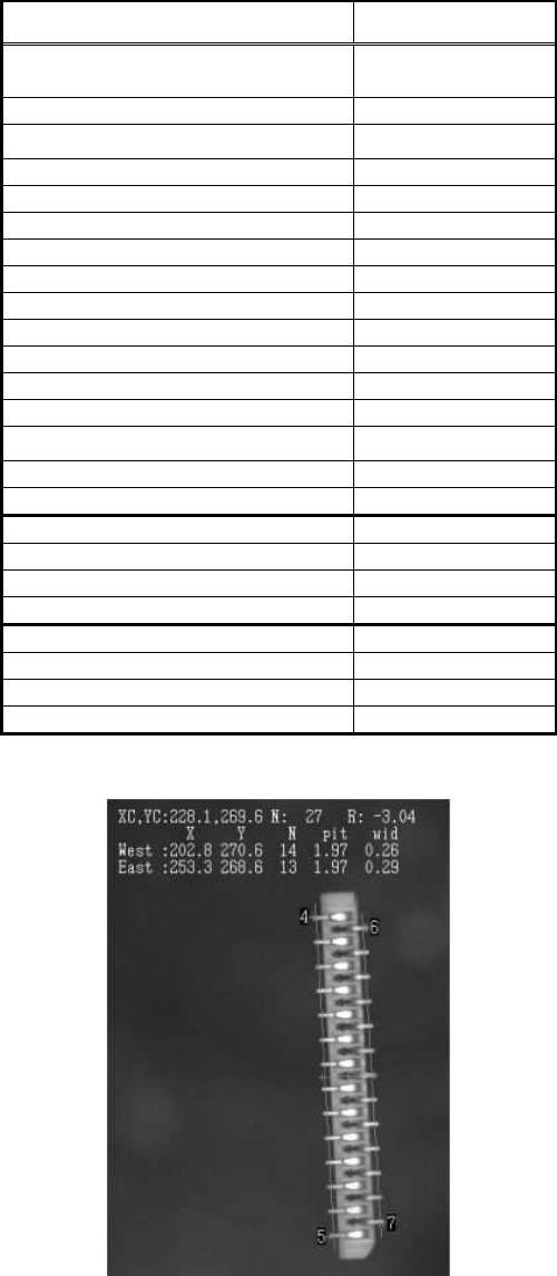
<< Recognition of connectors in a zigzag layout that are symmetrical on the upper and
lower sides>>
Items to be set Set value
Alignment Group
Connector
component
Alignment Type Connector NSEW
Comp. Threshold 50
Comp. Tolerance 30
Search Area (mm) 4.0
Body Size X (mm) 4.4
Body Size Y (mm) 32.0
Body Size Z (mm) 4.0
Cntr. Offset X (mm) 0.0
Cntr. Offset Y (mm) 0.0
Cntr. Offset R (mm) 0.0
Ruler Offset N 0
Ruler Offset S 0
Ruler Offset E 3
Ruler Offset W 3
Ruler Width 3
Lead Number E 13
Lead Pitch E (mm) 2.0
Lead Width E (mm) 0.3
Reflect LL. E(mm) 0.7
Lead Number W 14
Lead Pitch W (mm) 2.0
Lead Width W (mm) 0.3
Reflect LL. W (mm) 0.7
Table 54
Figure 62
83/178
IM-SMT-VSNDIC-0002-000
Recognition of connectors in a zigzag layout that are asymmetrical on the upper and lower side
<< Items to be set for Special 1 connectors >>
Items to be set Set value
Alignment Group Special
Alignment Type Special
Comp. Threshold 50
Comp. Tolerance 30
Search Area (mm) 3.0
Body Size X (mm) 3.0
Body Size Y (mm) 13.0
Body Size Z (mm) 3.0
Cntr. Offset X (mm) 0.0
Cntr. Offset Y (mm) 0.0
Cntr. Offset R (mm) 0.0
Ruler Width 3
Algorithm Special 1
Base Alignment Special
Vision Option 1 0
Vision Option 2 0
Vision Option 3 0
Common
Data
Vision Option 4 0
Items to be set Set Value
Lead Group E 1
Common
Ruler Offset E 3
Lead Number: 1E 8
Reflect LL.: 1E (mm) 0.5
Lead Width: 1E (mm) 0.2
Lead Pitch: 1E (mm) 2.0
Find Pos X: 1E (mm) 1.5
E
Direction
Group 1
Find Pos Y: 1E (mm) 7.5
Lead Group W 1
Common
Ruler Offset W 3
Lead Number: 1W 8
Reflect LL.: 1W (mm) 0.5
Lead Width: 1W (mm) 0.2
Lead Pitch: 1W (mm) 2.0
Find Pos X: 1W (mm) -1.5
W
Direction
Group 1
Find Pos Y: 1W (mm) 6.5
Table 55
These are recognized as Special 1 connectors. They are defined by offsetting the Find Pos Y
in the E and W directions by half of the pitch.