创建组件识别数据的方法.pdf - 第84页
84/178 IM-SMT-VSNDI C-0002 -000 Figure 63 Items to be set Set value Alignment Group S pecial Alignment T ype S pec ial Comp. Threshold 5 0 Comp. T olerance 30 Search Are a (mm) 4.0 Body Size X (m m) 3.2 Body Size Y (mm) …
83/178
IM-SMT-VSNDIC-0002-000
Recognition of connectors in a zigzag layout that are asymmetrical on the upper and lower side
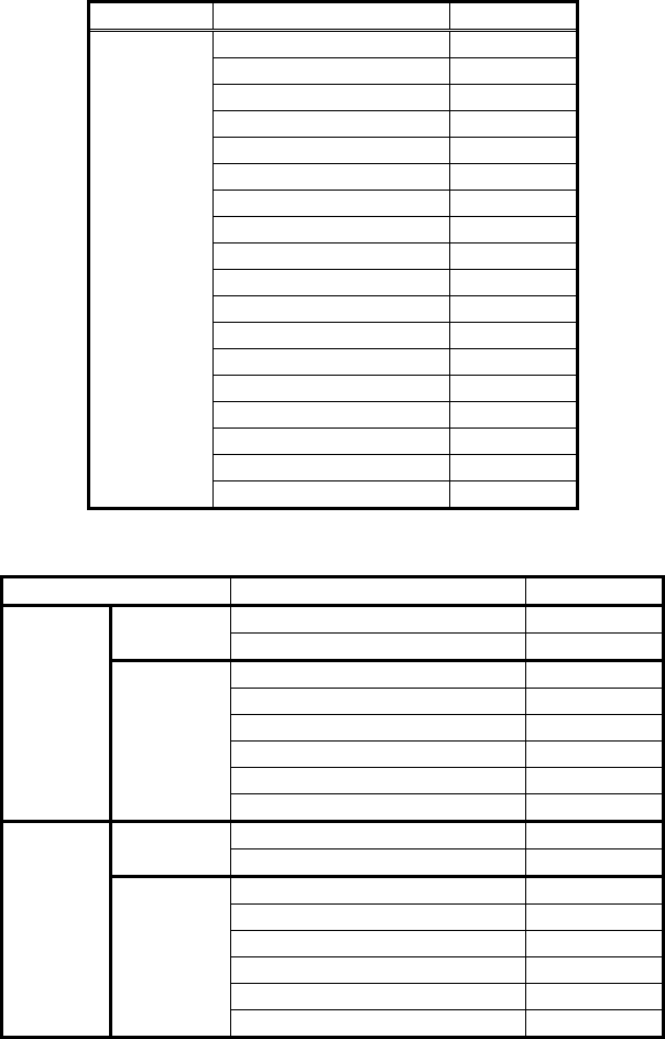
<< Items to be set for Special 1 connectors >>
Items to be set Set value
Alignment Group Special
Alignment Type Special
Comp. Threshold 50
Comp. Tolerance 30
Search Area (mm) 3.0
Body Size X (mm) 3.0
Body Size Y (mm) 13.0
Body Size Z (mm) 3.0
Cntr. Offset X (mm) 0.0
Cntr. Offset Y (mm) 0.0
Cntr. Offset R (mm) 0.0
Ruler Width 3
Algorithm Special 1
Base Alignment Special
Vision Option 1 0
Vision Option 2 0
Vision Option 3 0
Common
Data
Vision Option 4 0
Items to be set Set Value
Lead Group E 1
Common
Ruler Offset E 3
Lead Number: 1E 8
Reflect LL.: 1E (mm) 0.5
Lead Width: 1E (mm) 0.2
Lead Pitch: 1E (mm) 2.0
Find Pos X: 1E (mm) 1.5
E
Direction
Group 1
Find Pos Y: 1E (mm) 7.5
Lead Group W 1
Common
Ruler Offset W 3
Lead Number: 1W 8
Reflect LL.: 1W (mm) 0.5
Lead Width: 1W (mm) 0.2
Lead Pitch: 1W (mm) 2.0
Find Pos X: 1W (mm) -1.5
W
Direction
Group 1
Find Pos Y: 1W (mm) 6.5
Table 55
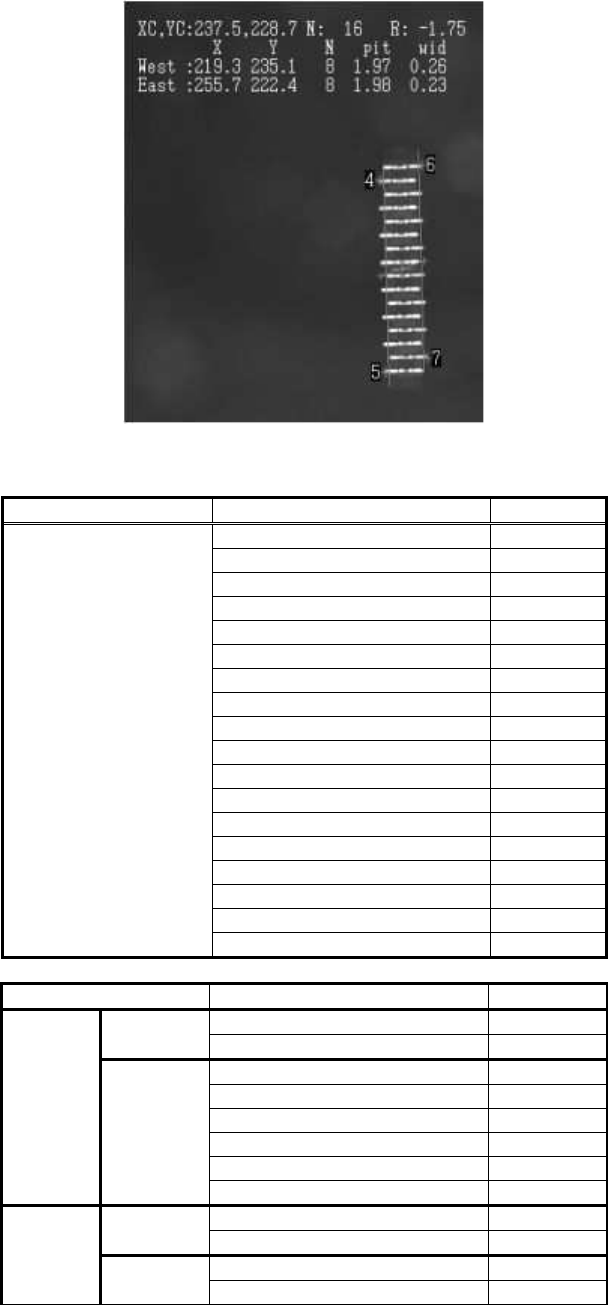
These are recognized as Special 1 connectors. They are defined by offsetting the Find Pos Y
in the E and W directions by half of the pitch.
84/178
IM-SMT-VSNDIC-0002-000
Figure 63
Items to be set Set value
Alignment Group Special
Alignment Type Special
Comp. Threshold 50
Comp. Tolerance 30
Search Area (mm) 4.0
Body Size X (mm) 3.2
Body Size Y (mm) 28.0
Body Size Z (mm) 3.0
Cntr. Offset X (mm) 0.0
Cntr. Offset Y (mm) 0.0
Cntr. Offset R (mm) 0.0
Ruler Width 3
Algorithm Special 1
Base Alignment Special
Vision Option 0
Vision Option 2 0
Vision Option 3 0
Common
Data
Vision Option 4 0
Items to be set Set value
Lead Group E 1
Common
Ruler Offset E 3
Lead Number: 1E 25
Reflect LL.: 1E (mm) 0.5
Lead Width: 1E (mm) 0.2
Lead Pitch: 1E (mm) 1.0
Find Pos X: 1E (mm) 1.6
E
Direction
Group 1
Find Pos Y: 1E (mm) 12.5
Lead Group W 1
Common
Ruler Offset W 3
Lead Number: 1W 25
W
Direction
Group 1
Reflect LL.: 1W (mm) 0.5
85/178
IM-SMT-VSNDIC-0002-000
Items to be set Set value
Lead Width: 1W (mm) 0.2
Lead Pitch: 1W (mm) 1.0
Find Pos X: 1W (mm) -1.6
Find Pos Y: 1W (mm) 12.0
Table 56
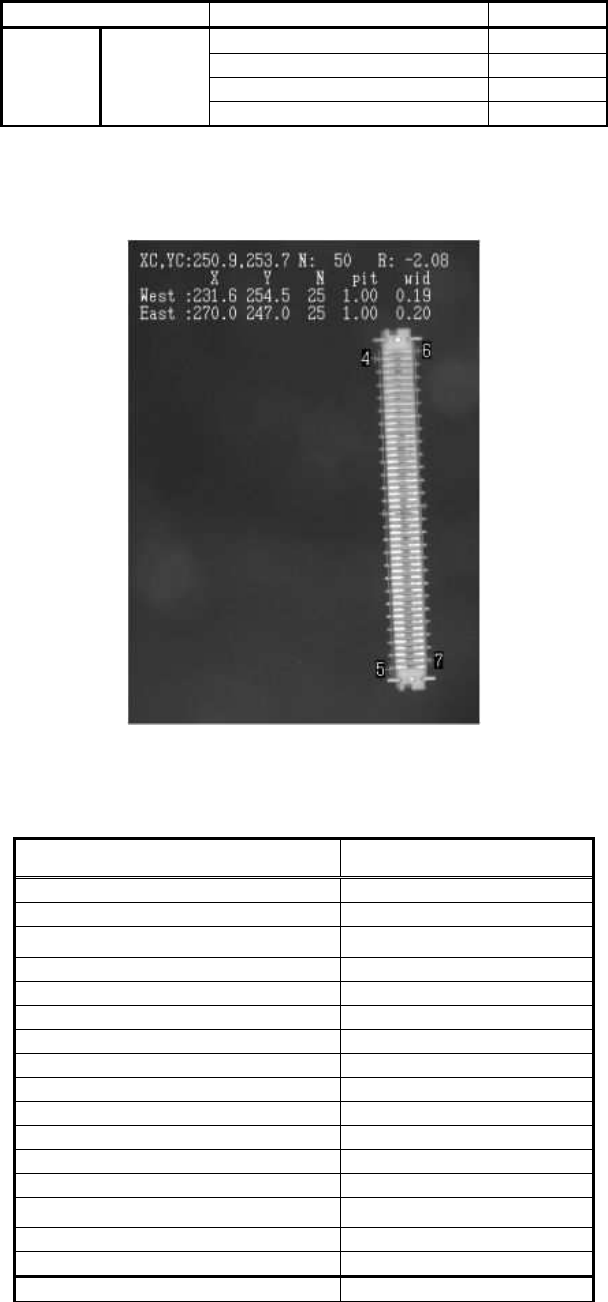
Recognition of connectors with fixed leads in a zigzag layout.
Fixed leads are ignored when definitions are made.
Figure 64
When performing recognition on the connectors that have leads both on outside and inside of
the component, only the leads on outside of the component are used for recognition.
Items to be set Set value
Alignment Group Connector
Alignment Type Con-NSEW
Comp. Threshold 50
Comp. Tolerance 30
Search Area (mm) 5.0
Body Size X (mm) 16.0
Body Size Y (mm) 40.0
Body Size Z (mm) 4.0
Cntr. Offset X (mm) 0.0
Cntr. Offset Y (mm) 0.0
Cntr. Offset R (mm) 0.0
Ruler Offset N 0
Ruler Offset S 0
Ruler Offset E 5
Ruler Offset W 5
Ruler Width 3
Lead Number E 60