创建组件识别数据的方法.pdf - 第148页
148/178 IM-SMT-VSNDI C-0002 -000 Note *3 : T his option parameter c onsists of one byte of data, and eac h bit has d ifferent meaning. << Mark-General purpose : Items to be set for c omponent s consists of multiple…
147/178
IM-SMT-VSNDIC-0002-000
Items to be set Set value
Explanation
Alignment Group Special Sets the component category.
Alignment Type Special Sets the component type.
Comp. Threshold
Sets the binarization level.
(If 0 is specified, the threshold is set
automatically.)
Comp. Tolerance Specifies the tolerance as a percentage.
Search Area (mm) Sets the range of the detection.
Body Size X (mm) Sets the size of the outer edge.
Body Size Y (mm) Sets the size of the outer edge.
Body Size Z (mm) Sets the size of the outer edge.
Cntr. Offset X (mm)
Sets the offset amount in the X direction
from the center position.
Cntr. Offset Y (mm)
Sets the offset amount in the Y direction
from the center position.
Cntr. Offset R (mm)
Sets the offset amount of the angle of
rotation.
Ruler Width 0 Not used.
Algorithm Special 4
Selects the recognition algorithm when
using a special algorithm.
Base Alignment As Mark
Selects the basic component type when
using a special algorithm.
Vision Option 1
*2
Sets option parameter 1.
Vision Option 2
*3
Sets option parameter 2.
Vision Option 3 0 Sets option parameter 3.
Common
Data
Vision Option 4
*1
Specifies the priority to perform “Cut
Inner Noise “/”Cut Outer Noise” function
and the object type.
(continued)
Note
*1
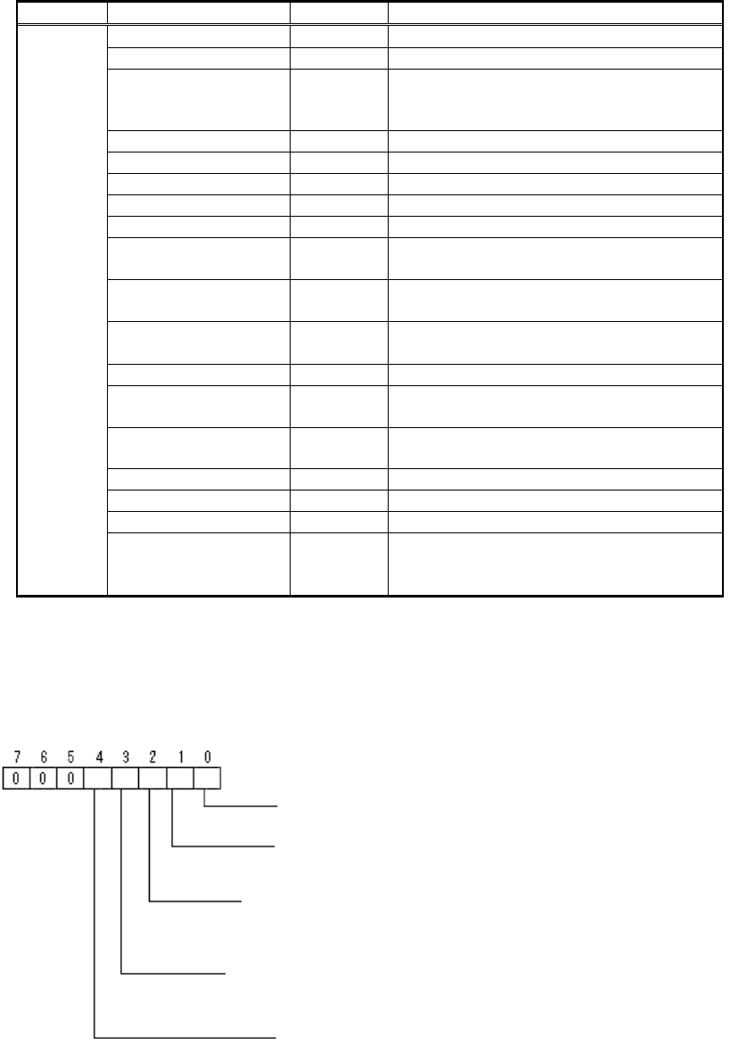
: This option parameter consists of one byte of data, and each bit has different
meaning. (Please refer to “2.12.3-3. Mark 2”, Note *3 for the details.)
Note
*2
: This option parameter consists of one byte of data, and each bit has different
meaning.
Bit position
Pitch check: (0: Not executed, 1: Executed)
Lead position check 0: Not executed 1: Executed.
(This checks to see if the lead is within the range specified
by the pitch x tolerance. If a check is carried out, the pitch
is input, even if there is only one lead.)
* Please refer to Appendix 4.
Method of setting the parameter for the distance between
the lead and
corner:
(
0: New 1: Previous
)
Trace retry: (0:No,
1: Yes)
The binarization method when the threshold is
0: Automatic binarizaiton, 1: P
-
tile binarization

148/178
IM-SMT-VSNDIC-0002-000
Note
*3
: This option parameter consists of one byte of data, and each bit has different
meaning.
<< Mark-General purpose : Items to be set for components consists of multiple parts >>
(continued)
Items to be set
Set
value
Explanation
Lead Group N
Sets the number of Lead Group.
(1 or 2)
Common
Ruler Offset N 0
Sets the offset amount of the
detection line in the N direction.
Lead Number: 1N
Sets the number of leads of
Group 1 in the N direction.
Reflect LL.: 1N (mm)
*4
Sets the lead length on the
image of Group 1 in the N
direction.
Lead Width: 1N (mm)
*4
Sets the width of the leads of
Group 1 in the N direction.
Lead Pitch: 1N (mm)
Sets the lead pitch of Group 1 in
the N direction.
Find Pos X: 1N (mm)
*5
Sets the reference position X for
the lead of Group 1 in the N
direction.
Group
1
Find Pos Y: 1N (mm)
*5
Sets the reference position Y for
the lead of Group 1 in the N
direction.
Lead Number: 2N
Sets the number of leads of
Group 2 in the N direction.
Reflect LL.: 2N (mm)
*4
Sets the lead length on the
image of Group 2 in the N
direction.
Lead Width: 2N (mm)
*4
Sets the width of the leads of
Group 2 in the N direction.
Lead Pitch: 2N (mm)
Sets the lead pitch of Group 2 in
the N direction.
Find Pos X: 2N (mm)
*5
Sets the reference position X for
the lead of Group 2 in the N
direction.
N
direction
Group
2
Find Pos Y: 2N (mm)
*5
Sets the reference position Y for
the lead of Group 2 in the N
direction.
Lead Group S
Sets the number of the Lead
Group (1 or 2).
Common
Ruler Offset S 0
Sets the offset amount of the
detection line in the S direction.
S
direction
Group
Lead Number: 1S
Sets the number of leads of
Group 1 in the S direction.
Bit position
Center Detection Algorithm:
0: Center of circumscribed rectangle
1: Center of rectangle composed of component inclination lines
passing through the center of gravity of each of the sides
2: Center of all leads

149/178
IM-SMT-VSNDIC-0002-000
Items to be set
Set
value
Explanation
Reflect LL.: 1S (mm)
*4
Sets the lead length on the
image of Group 1 in the S
direction.
Lead Width: 1S (mm)
*4
Sets the width of the leads of
Group 1 in the S direction.
Lead Pitch: 1S (mm)
Sets the lead pitch of Group 1 in
the S direction.
Find Pos X: 1S (mm)
*5
Sets the reference position X for
the lead of Group 1 in the S
direction.
1
Find Pos Y: 1S(mm)
*5
Sets the reference position Y for
the lead of Group 1 in the S
direction.
Lead Number: 2S
Sets the number of leads of
Group 2 in the S direction.
Reflect LL.: 2S (mm)
*4
Sets the lead length on the
image of Group 2 in the S
direction.
Lead Width: 2S (mm)
*4
Sets the width of the leads of
Group 2 in the S direction.
Lead Pitch: 2S (mm)
Sets the lead pitch of Group 2 in
the S direction.
Find Pos X: 2S (mm)
*5
Sets the reference position X for
the lead of Group 2 in the S
direction.
Group
2
Find Pos Y: 2S(mm)
*5
Sets the reference position Y for
the lead of Group 2 in the S
direction.
Lead Group E
Sets the number of the Lead
Group (1 or 2).
Common
Ruler Offset E 0
Sets the offset amount of the
detection line in the E direction.
Lead Number: 1E
Sets the number of leads of
Group 1 in the E direction.
Reflect LL.: 1E (mm)
*4
Sets the lead length on the
image of Group 1 in the E
direction.
Lead Width: 1E (mm)
*4
Sets the width of the leads of
Group 1 in the E direction.
Lead Pitch: 1E (mm)
Sets the lead pitch of Group 1 in
the E direction.
Find Pos X: 1E (mm)
*5
Sets the reference position X for
the lead of Group 1 in the E
direction.
Group
1
Find Pos Y: 1E(mm)
*5
Sets the reference position Y for
the lead of Group 1 in the E
direction.
Lead Number: 2E
Sets the number of leads of
Group 2 in the E direction.
E
direction
Group
2
Reflect LL.: 2E(mm)
*4
Sets the lead length on the
image of Group 2 in the E
direction.