创建组件识别数据的方法.pdf - 第115页
115/178 IM-SMT-VSNDI C-0002 -000 The following is the actual example of r ecognition. <Color resistor > <Diode> Figure 88 2.1 1.3 Bare chip <<Items to be set for Bare chips>> Items to be set Set v…
114/178
IM-SMT-VSNDIC-0002-000
2.11.2
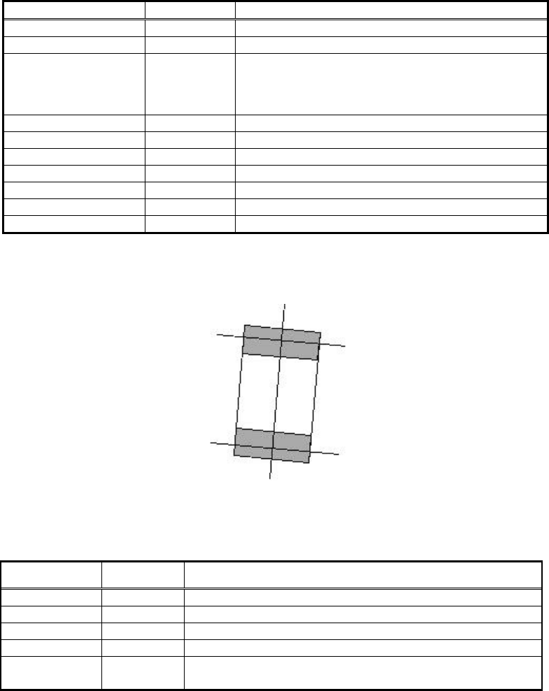
MELF chips
<<Items to be set for MELF chips>>
Items to be set Set value Explanation
Alignment Group Chip Sets the component category.
Alignment Type MELF chip Sets the component type.
Comp. Threshold
Sets the detection level difference for lead
detection.
(See “Appendix 2. Detection level differences used to
detect leads (threshold value)”.)
Comp. Tolerance Specifies the shape tolerance as a percentage.
Search Area (mm) Sets the range of the detection.
Body Size X (mm) Sets the size of the outer edge.
Body Size Y (mm) Sets the size of the outer edge.
Body Size Z (mm) Sets the size of the outer edge.
Ruler Offset Sets the offset amount for the detection line.
Lead Width (mm) Sets the lead width.
Table 78
The detection line is drawn in “‡” shape.
Figure 87
[Recognition check items]
Items Yes / No Notes
Body Size May exist
Only Body Size Y is checked
Lead pitch No
Lead width Yes
Lead length No
Lead position
Yes
Checks whether the center of the detected lead tip is in
the range of Body Size Y x tolerance.
Table 79
115/178
IM-SMT-VSNDIC-0002-000
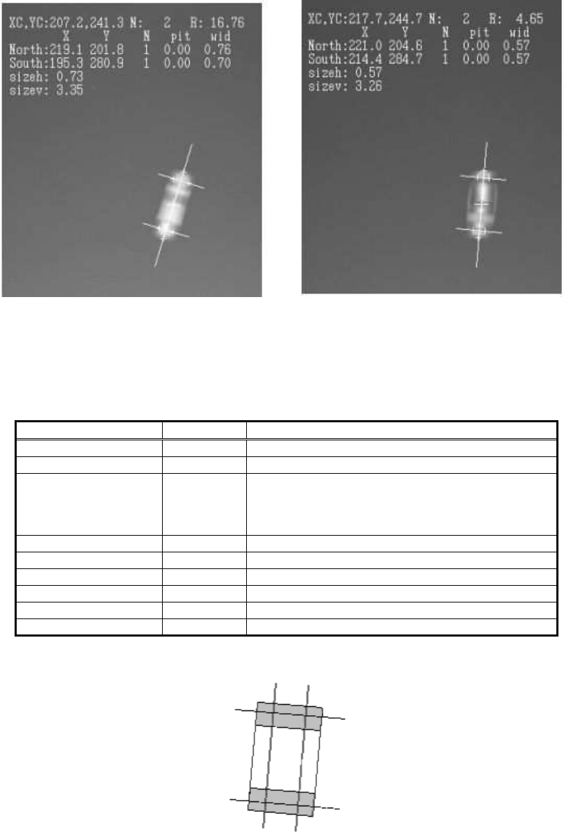
The following is the actual example of recognition.
<Color resistor> <Diode>
Figure 88
2.11.3 Bare chip
<<Items to be set for Bare chips>>
Items to be set Set value Explanation
Alignment Group Chip Sets the component category.
Alignment Type Bare chip
Sets the component type.
Comp. Threshold
Sets the detection level difference for lead
detection.
(See “Appendix 2. Detection level differences used to
detect leads (threshold value)”.)
Comp. Tolerance Specifies the shape tolerance as a percentage.
Search Area (mm) Sets the range of the detection.
Body Size X (mm) Sets the size of the outer edge.
Body Size Y (mm) Sets the size of the outer edge.
Body Size Z (mm) Sets the size of the outer edge.
Ruler Offset Sets the offset amount for the detection line.
Table 80
Figure 89
116/178
IM-SMT-VSNDIC-0002-000
[Recognition check items]
Items Yes / No Notes
Body Size May exist
Only Body Size Y is checked.
Lead pitch No
Lead width Yes
Lead length No
Lead position
Yes
Checks whether the center of the detected lead tip is in
the range of Body Size Y x tolerance.
Table 81
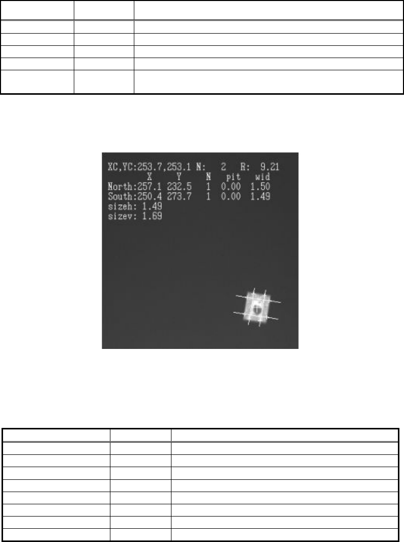
The following is the actual example of the recognition.
Figure 90
2.11.4. Cylindrical chip
<<Items to be set for Cylindrical chips>>
Items to be set Set value Explanation
Alignment Group Chip Sets the component category.
Alignment Type Cylinder Sets the component type.
Comp. Threshold Sets the binarization level.
Comp. Tolerance Specifies the shape tolerance as a percentage.
Search Area (mm) Sets the range of the detection.
Body Diameter Sets the size of the outer edge.
Body Size Z (mm) Sets the size of the outer edge.
Ruler Offset
Table 82
This mode is used for the recognition of the cylindrical components. No component angle is
required.