创建组件识别数据的方法.pdf - 第25页
25/178 IM-SMT-VSNDI C-0002 -000 Items to be set Set value Algorithm Base Alignm ent Mini-Tr /SOT Vision Option 1 0 Vision Option 2 0 Vision Option 3 0 Vision Option 4 0 Items to be set Set value Lead Group N 2 Comm on Ru…
24/178
IM-SMT-VSNDIC-0002-000
Items to be set Set value
Ruler Offset 3
Ruler Width 1
Lead Number N 2
Lead Number S 2
Reflct LL 0.5
Lead Width (mm) 0.4
Lead Pitch N (mm) 2.0
Lead Pitch S (mm) 2.0
Table 12
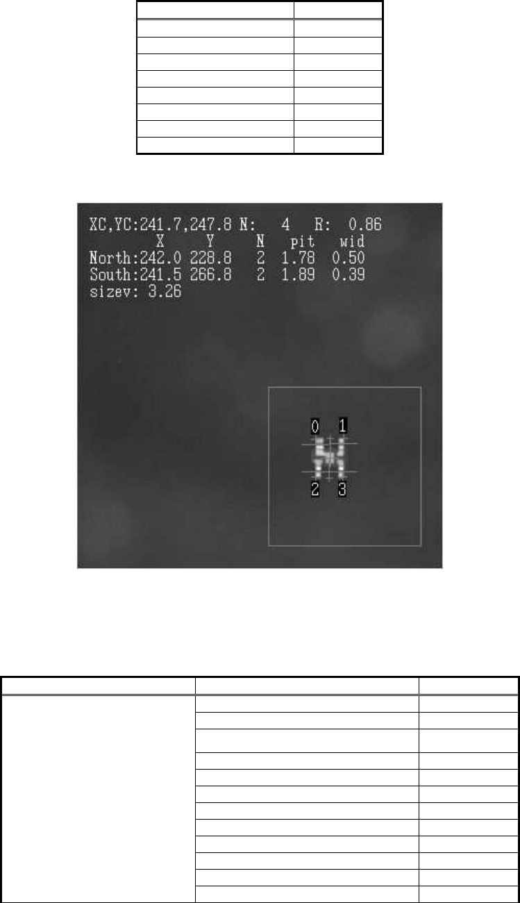
<Recognition result with standard data>
Figure 16
In order to avoid this, the data corresponds to the component shape should be created.
Special mode is used in order to define the leads in the N direction as two Lead Groups.
<Items to be set for mini-mold transistors and SOTs>
Items to be set Set value
Alignment Group Special
Alignment Type Special
Comp. Threshold 50
Comp. Tolerance 30
Search Area (mm) 5.0
Body Size X (mm) 3.0
Body Size Y (mm) 3.2
Body Size Z (mm) 1.2
Cntr. Offset X (mm) 0.0
Cntr. Offset Y (mm) 0.0
Cntr. Offset R (mm) 0.0
Common Data
Ruler Width 1
25/178
IM-SMT-VSNDIC-0002-000
Items to be set Set value
Algorithm
Base Alignment Mini-Tr /SOT
Vision Option 1 0
Vision Option 2 0
Vision Option 3 0
Vision Option 4 0
Items to be set Set value
Lead Group N 2
Common
Ruler Offset N 3
Lead Number : 1N 1
Reflect LL.: 1N (mm) 0.5
Lead Width: 1N (mm) 0.6
Lead Pitch: 1N (mm) 0.0
Find Pos X: 1N (mm) - 0.9
Group 1
Find Pos Y: 1N (mm) 1.6
Lead Number : 2N 1
Reflect LL.: 2N (mm) 0.5
Lead Width: 2N (mm) 0.6
Lead Pitch: 2N (mm) 0.0
Find Pos X: 2N (mm) 1.0
N Direction
Group 2
Find Pos Y: 2N (mm) 1.6
Lead Group S 1
Common
Ruler Offset S 3
Lead Number : 1S 2
Reflect LL.: 1S (mm) 0.5
Lead Width: 1S(mm) 0.4
Lead Pitch: 1S (mm) 2.0
Find Pos X: 1S (mm) -1.0
S Direction
Group 1
Find Pos Y: 1S (mm) -1.6
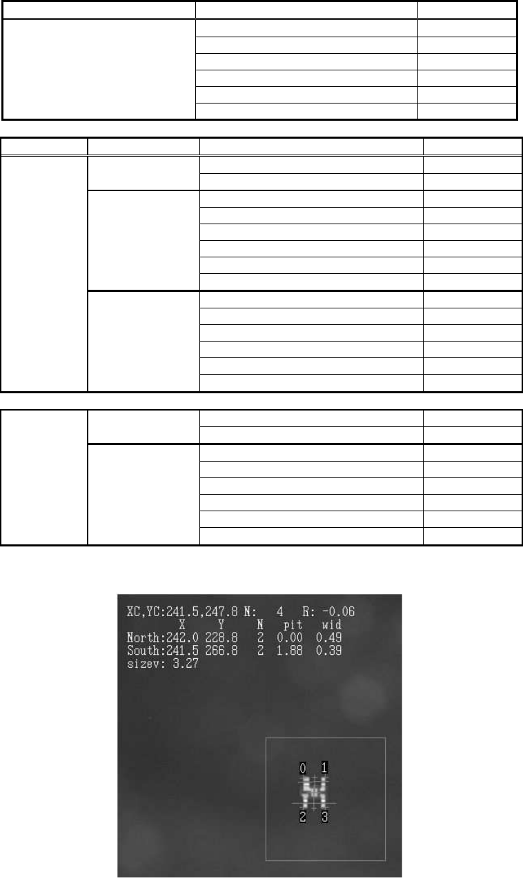
Table 13
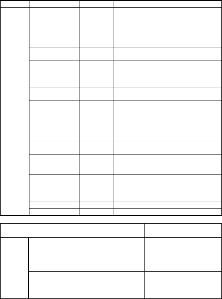
<Recognition result with special data>
Figure 17
26/178
IM-SMT-VSNDIC-0002-000
This makes it possible to obtain the results that are not offset.
2.2.1 Mini-mold transistor / SOTs Special –(1)
Though the “Special” mode is provided for recognizing the trimmer capacitors, variable
resistors and other components, the “Power Transistor” mode (See “2.3. P-Tr” ) or the
“Special Quad.” mode (See “2.12.4. Special Quad”) are recommendable to be used for these
components. (*Please note that the operation is not covered under YAHAMA guaranty.)
<Items to be set for mini-mold transistor and SOTs (Special 1)>
Items to be set Set value
Explanation
Alignment Group
Special Sets the component category.
Alignment Type Special Sets the component type.
Comp. Threshold
Sets the detection level difference for
lead detection.
(See “Appendix 2. Detection
level differences used to detect leads
(threshold value)”)
Comp. Tolerance
Specifies the tolerance of the lead pitch
as a percentage.
Search Area
(mm)
Sets the range of the detection.
Body Size X
(mm)
Sets the size of the outer edge.
Body Size Y
(mm)
Sets the size of the outer edge.
Body Size Z
(mm)
Sets the size of the outer edge.
Cntr. Offset X
(mm)
Sets the offset amount in the X direction
from the center position.
Cntr. Offset Y
(mm)
Sets the offset amount in the Y direction
from the center position.
Cntr. Offset R
(mm)
Sets the offset amount of the angle of
rotation.
Ruler Width
Algorithm Special 1
Selects the recognition algorithm when
using a special algorithm.
Base Alignment
Mini-Tr
/SOT
Selects the basic component type when
using a special algorithm.
Vision Option 1 0 Sets option parameter 1.
Vision Option 2 0 Sets option parameter 2.
Vision Option 3 0 Sets option parameter 3.
Common
Data
Vision Option 4 0 Sets option parameter 4.
Items to be set
Set
value
Explanation
Lead Group N 1
Sets the number of Lead
Group in the N direction. (1)
Common
Ruler Offset N
Sets the offset amount for
the detection line in the N
direction.
Lead Number: 1N
Sets the number of leads in
the N direction.
N
Direction
Group
1
Reflect LL.: 1N (mm)
Sets the lead length on the
image in the N direction.