创建组件识别数据的方法.pdf - 第129页
129/178 IM-SMT-VSNDI C-0002 -000 2.12.3. Mark types There are a num ber of algorithms available for recogn ition of m ark types. The ta rget object i s binarized, then the component is detected from the detec ted target …
128/178
IM-SMT-VSNDIC-0002-000
Items to be set
Set
value
Explanation
Find Pos X: 2W(mm)
Sets the reference position X for
the lead of Group 2 in the W
direction.
Find Pos Y: 2Wmm)
Sets the reference position Y for
the lead of Group 2 in the W
direction.
Table 88
2.12.2. Odd-shape chips
<<Items to be set for odd-shape chips>>
Items to be set Set value
Explanation
Alignment Group Special Sets the component category.
Alignment Type
Odd.
Chip
Sets the component type.
Comp. Threshold
Sets the difference of the detection level for the lead
detection.
(See “Appendix 2. Detection level differences used to
detect leads (threshold value)”.)
Comp. Tolerance Specifies the tolerance of the shape as a percentage.
Search Area (mm) Sets the range of the detection.
Body Size X (mm) Sets the size of the outer edge.
Body Size Y (mm) Sets the size of the outer edge.
Body Size Z (mm) Sets the size of the outer edge.
Ruler Offset Sets the offset amount of the detection line.
Table 89
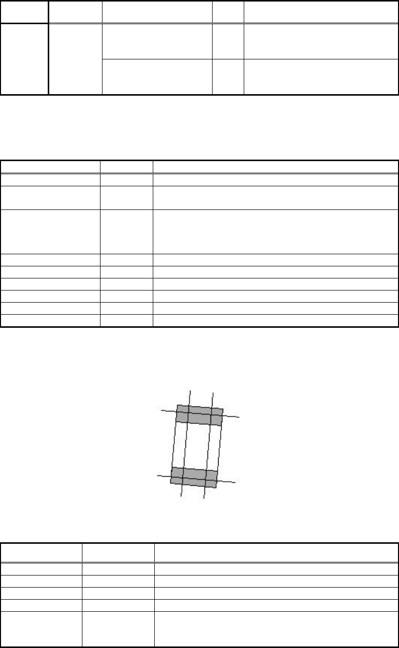
It is possible to recognize the lead regardless of whether it is black or white. (Recognition is
performed by using both black and white leads, and whichever produces a satisfactory result
is adopted.)
Figure 98
[Recognition check items]
Items Yes / No Notes
Body Size May exist Only Body Size Y is checked.
Lead pitch No
Lead width Yes
Lead length No
Lead position No
Checks if the center of the lead tip position of the
detected lead is in the range of Body Size Y x
tolerance.
Table 90
129/178
IM-SMT-VSNDIC-0002-000
2.12.3. Mark types
There are a number of algorithms available for recognition of mark types.
The target object is binarized, then the component is detected from the detected target object.
It is possible to use the fixed threshold and the automatic threshold for binarization.
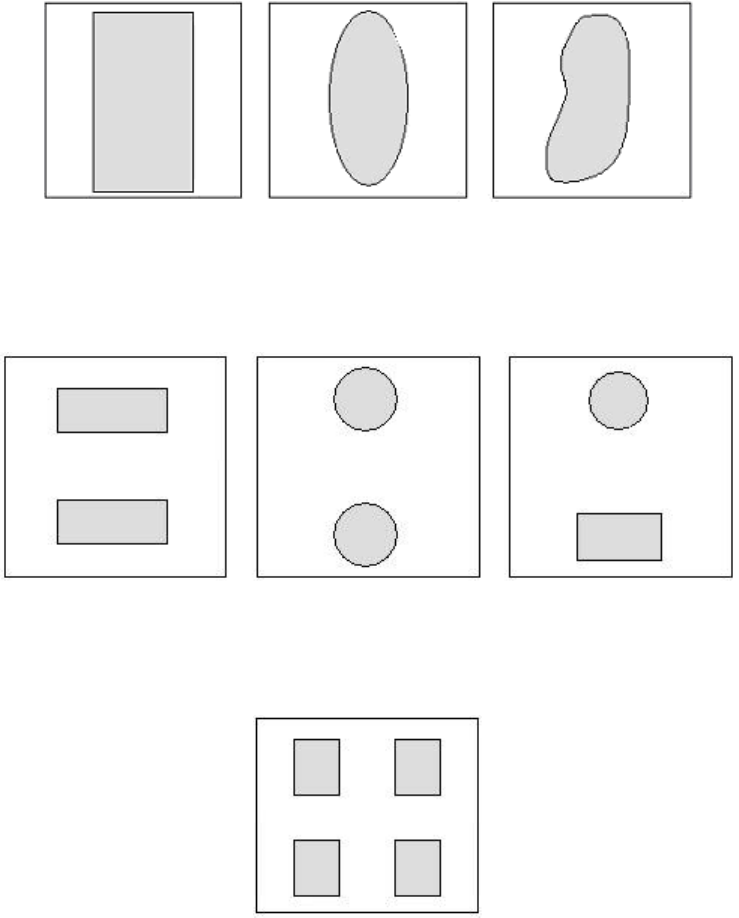
1) Special components: Mark type (mark 1)
This is used for recognition of objects that consist of a single part as shown in
Figure 99
.
Figure 99
2) Algorithm: Special 1 (mark line)
3) Algorithm: Special 2 (mark 2)
This is used for recognition of objects that consist of two parts as shown in
Figure 100
.
Figure 100
4) Algorithm: Special 3 (mark 4)
This is used for recognition of objects that consist of four parts as shown in
Figure 101
.
Figure 101
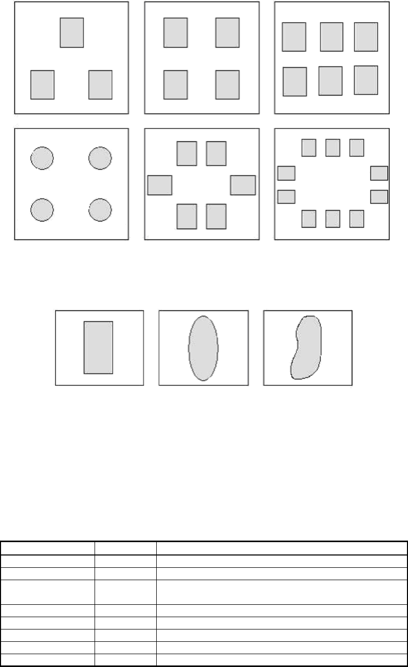
5) Algorithm: Special 4 (mark, general-purpose)
This is used for recognition of objects that consist of multiple parts, as shown in
Figure 102.
130/178
IM-SMT-VSNDIC-0002-000
Figure 102
2.12.3-1. Mark 1
This is used for recognition of objects that consist of a single part as shown in
Figure 103
.
Figure 103
The target object is binarized, then the component is detected from the detected target object.
This mode can be used for recognition of the irregular shaped components.
It is possible to use the fixed threshold and the automatic threshold for binarization.
The component center is determined to be the center of gravity position, and the inclination
is determined to be the inclination of the axis.
The correct inclination of components that are close to the circular or square shape cannot be
obtained as they have no main axis.
White objects are normally recognized, but it is also possible to detect black objects on
a white background.
<< Items to be recognized for Mark 1 marks >>
Items to be set Set value Explanation
Alignment Group Special Sets the component category.
Alignment Type Mark Sets the component type.
Comp. Threshold
Sets the binarization level.
(If 0 is specified, the threshold is set automatically.)
Comp. Tolerance Specifies the tolerance of the shape as a percentage.
Search Area (mm)
Sets the range of the detection.
Body Size X (mm)
Sets the size of the outer edge.
Body Size Y (mm)
Sets the size of the outer edge.
Body Size Z (mm)
Sets the size of the outer edge.