创建组件识别数据的方法.pdf - 第24页
24/178 IM-SMT-VSNDI C-0002 -000 Items to be set Set value Ruler Offset 3 Ruler W idth 1 Lead Num ber N 2 Lead Num ber S 2 Reflct LL 0.5 Lead W idth (mm ) 0.4 Lead Pitch N (m m) 2.0 Lead Pitch S (m m) 2.0 Table 12 <Rec…
23/178
IM-SMT-VSNDIC-0002-000
there is, it is determined to be an error. (Some versions are not equipped with this
function.)
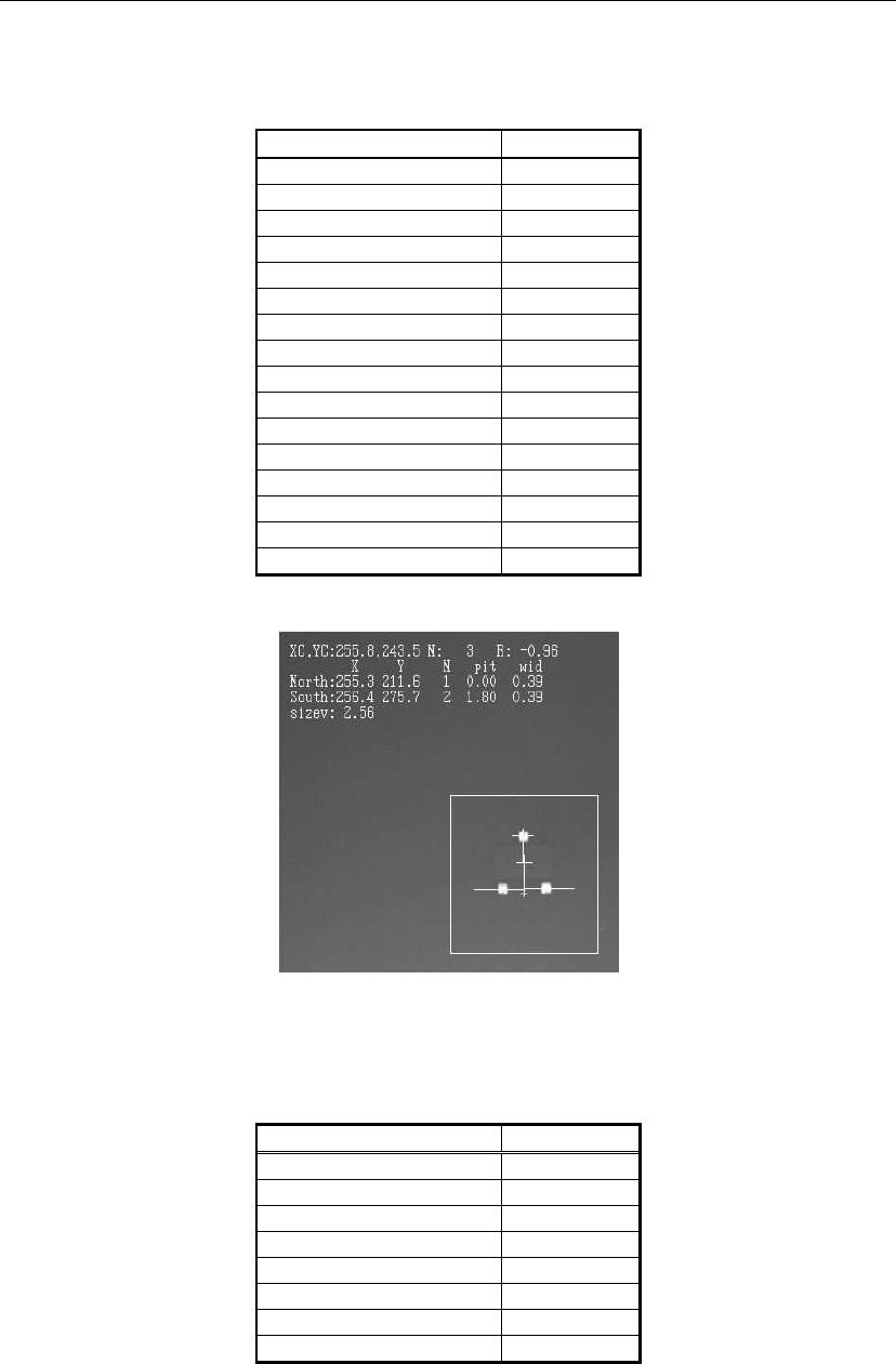
Table 11 is the example of actual definitions and the recognition results.
<< Items to be set for Mini-mold trasnsistors / SOTs >>
Items to be set Set value
Alignment Group IC
Alignment Type Mini-Tr/SOT
Comp. Threshold 45
Comp. Tolerance 20
Search Area (mm) 2.0
Body Size X (mm) 2.9
Body Size Y (mm) 2.6
Body Size Z (mm) 1.1
Ruler Offset 4
Ruler Width 1
Lead Number N 1
Lead Number S 2
Reflct LL 0.3
Lead Width (mm) 0.3
Lead Pitch N (mm) 0
Lead Pitch S (mm) 1.75
Table 11
Figure 15
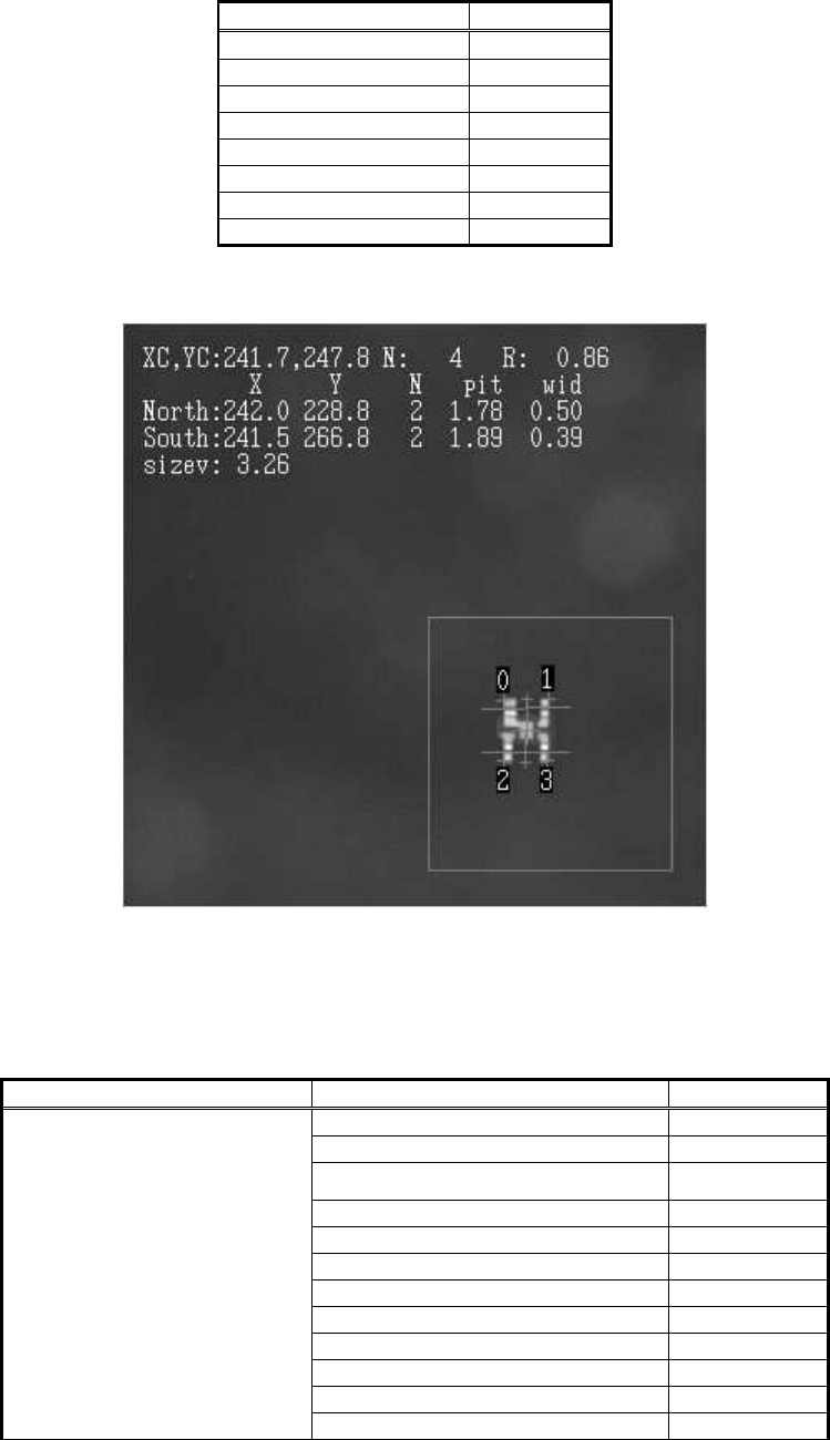
If the LED that has four leads and the lead width of one of the lead is different from the others
is recognized by standard mini-transistor /SOT recognition data, the correct result cannot be
obtained due to the different lead width.
Items to be set Set value
Alignment Group IC
Alignment Type Mini-Tr/SOT
Comp. Threshold 50
Comp. Tolerance 30
Search Area (mm) 5.0
Body Size X (mm) 3.0
Body Size Y (mm) 3.2
Body Size Z (mm) 1.2
24/178
IM-SMT-VSNDIC-0002-000
Items to be set Set value
Ruler Offset 3
Ruler Width 1
Lead Number N 2
Lead Number S 2
Reflct LL 0.5
Lead Width (mm) 0.4
Lead Pitch N (mm) 2.0
Lead Pitch S (mm) 2.0
Table 12
<Recognition result with standard data>
Figure 16
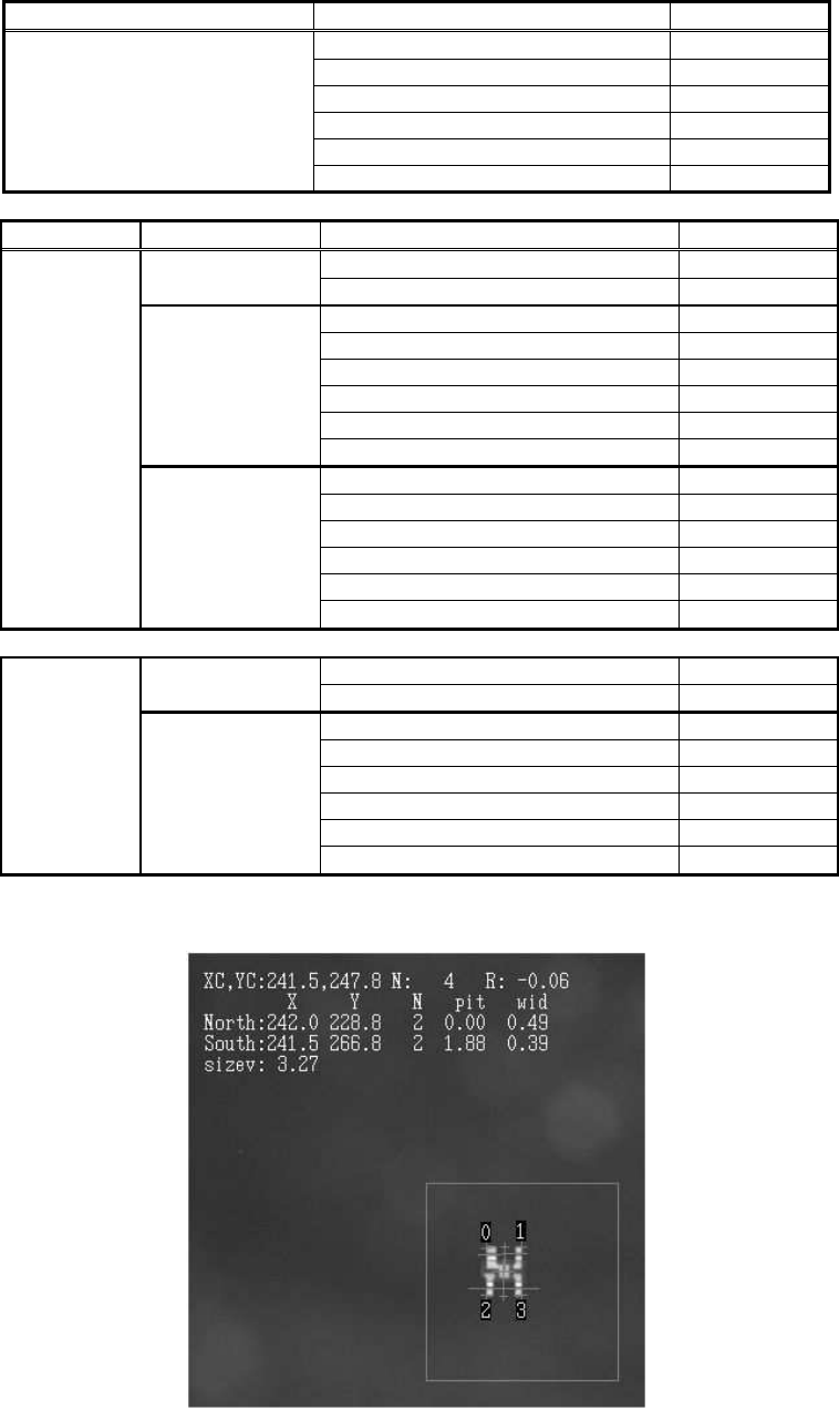
In order to avoid this, the data corresponds to the component shape should be created.
Special mode is used in order to define the leads in the N direction as two Lead Groups.
<Items to be set for mini-mold transistors and SOTs>
Items to be set Set value
Alignment Group Special
Alignment Type Special
Comp. Threshold 50
Comp. Tolerance 30
Search Area (mm) 5.0
Body Size X (mm) 3.0
Body Size Y (mm) 3.2
Body Size Z (mm) 1.2
Cntr. Offset X (mm) 0.0
Cntr. Offset Y (mm) 0.0
Cntr. Offset R (mm) 0.0
Common Data
Ruler Width 1
25/178
IM-SMT-VSNDIC-0002-000
Items to be set Set value
Algorithm
Base Alignment Mini-Tr /SOT
Vision Option 1 0
Vision Option 2 0
Vision Option 3 0
Vision Option 4 0
Items to be set Set value
Lead Group N 2
Common
Ruler Offset N 3
Lead Number : 1N 1
Reflect LL.: 1N (mm) 0.5
Lead Width: 1N (mm) 0.6
Lead Pitch: 1N (mm) 0.0
Find Pos X: 1N (mm) - 0.9
Group 1
Find Pos Y: 1N (mm) 1.6
Lead Number : 2N 1
Reflect LL.: 2N (mm) 0.5
Lead Width: 2N (mm) 0.6
Lead Pitch: 2N (mm) 0.0
Find Pos X: 2N (mm) 1.0
N Direction
Group 2
Find Pos Y: 2N (mm) 1.6
Lead Group S 1
Common
Ruler Offset S 3
Lead Number : 1S 2
Reflect LL.: 1S (mm) 0.5
Lead Width: 1S(mm) 0.4
Lead Pitch: 1S (mm) 2.0
Find Pos X: 1S (mm) -1.0
S Direction
Group 1
Find Pos Y: 1S (mm) -1.6
Table 13
<Recognition result with special data>
Figure 17