创建组件识别数据的方法.pdf - 第62页
62/178 IM-SMT-VSNDI C-0002 -000 Figure 49 As shown in Fig ure 49 , this recognitio n mode is use d when there is a gap in the row of leads . It is possible to define the com ponents that have le ads not onl y in two dire…

61/178
IM-SMT-VSNDIC-0002-000
Items to be set Set value
Explanation
Ruler Offset E
Sets the offset amount for the detection line in
the E direction.
Ruler Offset W
Sets the offset amount for the detection line in
the W direction.
Ruler Width
Lead Number N
Sets the number of leads in the N direction.
(Includes the missing part)
Lead Pitch N (mm) Sets the lead pitch in the N direction.
Lead Width N (mm) Sets the lead width in the N direction.
Reflect LL. N (mm)
Sets the lead length on the image in the N
direction.
Off Lead Start N
Sets the start position of lead gaps in the N
direction.
Off Lead End N
Sets the end position of lead gaps in the N
direction.
Lead Number S
Sets the number of leads in the S direction.
(Includes the missing part)
Lead Pitch S (mm) Sets the lead pitch in the S direction.
Lead Width S (mm) Sets the lead width in the S direction.
Reflect LL. S (mm)
Sets the lead length on the image in the S
direction.
Off Lead Start S
Sets the start position of lead gaps in the S
direction.
Off Lead End S
Sets the end position of lead gaps in the S
direction.
Lead Number E
Sets the number of leads in the E direction.
(Includes the missing part)
Lead Pitch E (mm) Sets the lead pitch in the E direction.
Lead Width E (mm) Sets the lead width in the E direction.
Reflect LL. E (mm)
Sets the lead length on the image in the E
direction.
Off Lead Start E
Sets the start position of lead gaps in the E
direction.
Off Lead End E
Sets the end position of lead gaps in the E
direction.
Lead Number W
Sets the number of leads in the W direction.
(Includes the missing part)
Lead Pitch W (mm) Sets the lead pitch in the W direction.
Lead Width W (mm) Sets the lead width in the W direction.
Reflect LL. W (mm)
Sets the lead length on the image in the W
direction.
Off Lead Start W
Sets the start position of lead gaps in the W
direction.
Off Lead End W
Sets the end position of lead gaps in the W
direction.
Table 39
62/178
IM-SMT-VSNDIC-0002-000
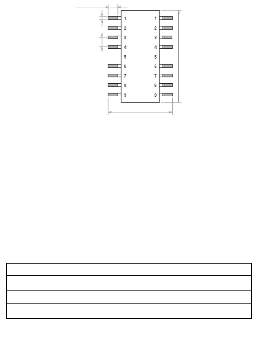
Figure 49
As shown in Figure 49
,
this recognition mode is used when there is a gap in the row of leads.
It is possible to define the components that have leads not only in two directions, but also in
one direction, three direction and four directions.
The numbers of the leads that start and end the gap are specified as the gap start/end
parameters.
In the example of
Figure 49,
the values would be as follows:
Lead Number: 9
Off Lead start: 5
Off Lead end: 5
When performing recognition of the components that have leads in two directions (E-W),
the recognition method is the same as that of SOJs. The others are the same as connector
component recognition.
[Recognition check items]
Items Yes / No Notes
Body Size No
Lead pitch Yes The pitch in the direction with one lead is not checked.
Lead width May exist
Checks only when the lead width is more than 1.0mm.
(Note 1)
Reflect LL No
Find Pos No
Table 40
Note:
“Lead width” check may not be available for some old software versions.
Lead length
Lead width
Lead Pitch
Body Size Y
Body Size Y

63/178
IM-SMT-VSNDIC-0002-000
The following is the actual example of the recognition.
<<Items to be set for Off Lead recognition >>
Items to be set Set value
Alignment Group IC
Alignment Type Off Lead
Comp. Threshold 50
Comp. Tolerance 30
Search Area (mm) 6.0
Body Size X (mm) 8.0
Body Size Y (mm) 17.0
Body Size Z (mm) 3.5
Cntr. Offset X (mm) 0.0
Cntr. Offset Y (mm) 0.0
Cntr. Offset R (mm) 0.0
Ruler Offset N 0
Ruler Offset S 0
Ruler Offset E 5
Ruler Offset W 5
Ruler Width 3
Lead Number E 13
Lead Pitch E (mm) 1.27
Lead Width E (mm) 0.43
Reflect LL. E (mm) 1.0
Off Lead Start E 6
Off Lead End E 8
Lead Number W 13
Lead Pitch W (mm) 1.27
Lead Width W (mm) 0.43
Reflect LL. W (mm) 1.0
Off Lead Start W 6
Off Lead End W 8
Table 41