OptimaUserManual.pdf - 第107页
OPT IMA PAL SO FTW ARE Opti ma User M anual 101 OPTIMA P A L SOFT W A RE This section of the Optima User Manual provides detailed descri ptions of the Optima P AL so ft ware us ed fo r p ro grammin g logic de vices . I f…
OPTIMA PROM SOFTWARE
Optima User Manual
100
OPTIMA PAL SOFTWARE
Optima User Manual
101
OPTIMA PAL SOFTWARE
This section of the Optima User Manual provides detailed descriptions of the Optima
PAL software used for programming logic devices. If you wish to get started
programming logic devices quickly, go to the QUICK START section of the Optima
User Manual.
Main Programming Screen
Once the device has been selected, the Main Programming screen for the Optima PAL
software will appear:
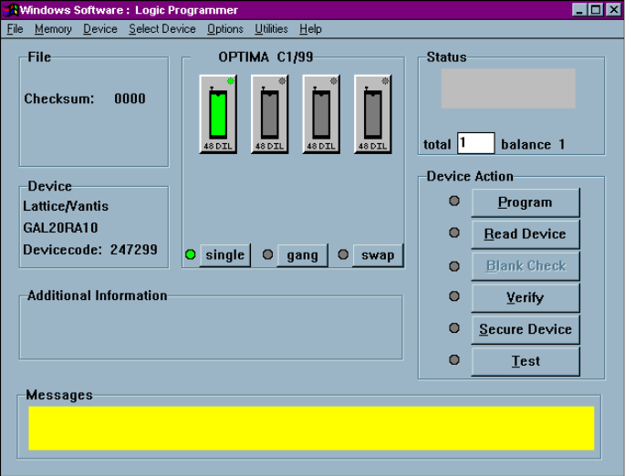
PAL software Main Programming screen
OPTIMA PAL SOFTWARE
Optima User Manual
102
The Main Programming screen is divided into these areas:
x File—contains information regarding the checksum of the data currently in RAM
and the usable address range of the device
x Device—contains information related to the device to be processed. The
Devicecode: field contains a unique identification code for the device selected.
This code is used by the optional TaskLink Windows software.
x OPTIMA Xx/XX—contains information about the PAL software version, the
TOPs installed on the programmer base, and the programming mode (single,
gang, or swap).
x Status—provides the status of the last device programmed
(PASS/FAIL/CHECK), the total number of devices to be processed (this field is
editable), and the number of devices remaining to be processed.
x Device Action—provides quick access to the most commonly used operations.
There are buttons for Program, Read Device, Blank Check, Verify, Secure Device
and Test operations.
x Additional information—contains any additional information that may be
required to process the selected devices, such as a specialized adapter, etc.
x Messages—contains any additional messages that describe various conditions
related to the processing of the selected device. Messages that may appear
include references to specialized adapters, settings that have been changed to
their non-default conditions, and others.
The area titled Optima Xx/XX contains several controls that determine the site(s) to
be used for programming, the TOPs installed on the site(s), and the programming
modes of operation. This section contains a virtual layout of the programmer in use.
If the programmer is an Optima Light, then one programmer site is shown, and the
TOP that has been installed is shown. If the programmer is an Octal, then eight sites
are displayed (arranged numerically from left to right, top to bottom, with Site #1 at
the upper left and Site #8 at the lower right), as well as indicators of the TOPs
installed on each site. If no TOPs are installed on one or more of the sites, those sites
will be displayed as NO TOP.