OptimaUserManual.pdf - 第89页
OPTIMA PROM SOF TW AR E Opti ma User M anual 83 The Optima softw are contains a convenient tool for isol ating the cause of a continui ty fa ilur e. Selec tin g the < Di sp la y > option presents you w ith a packag…
OPTIMA PROM SOFTWARE
Optima User Manual
82
After the automatic blank check is completed, the device will then be programmed
using the algorithm defined by the manufacturer. Intelligent programming is used to
keep programming time to a minimum. The intelligent programming algorithm is
selected automatically when the device type is selected.
After programming, the device will be verified to confirm proper programming. If
there are any errors in verification, you can create a detailed report of the errors on the
screen (see Device>Verify section). If the device vendor specifies it, verification will
be done at the V
cc
high and V
cc
low levels in accordance with manufacturer’s
specifications.
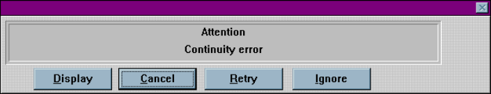
If the device is improperly inserted into the socket, the device is defective, or the
programming TOP is faulty, then a continuity message appears:
Continuity error
A yellow light on the TOP itself, as well as a yellow light on the TOP icon on the
Main Programming screen, identifies the socket with the continuity error. The
software prompts you to <Display> the pin(s) in error, <Cancel> the operation,
<Retry> the operation, or <Ignore> the error and continue.
OPTIMA PROM SOFTWARE
Optima User Manual
83
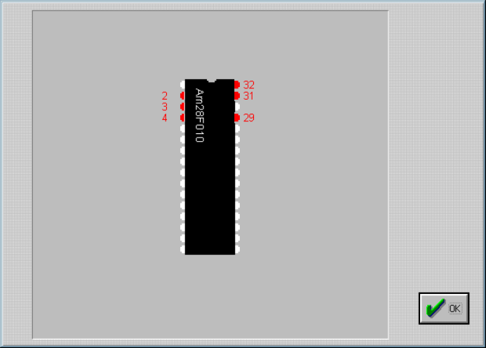
The Optima software contains a convenient tool for isolating the cause of a continuity
failure. Selecting the <Display> option presents you with a package diagram
outlining the pin(s) that are believed to be causing the failure:
Pinmap showing continuity failures; pins displayed here in gray are not making
proper contact. On user interface, pins not making proper contact are displayed in
red.
OPTIMA PROM SOFTWARE
Optima User Manual
84
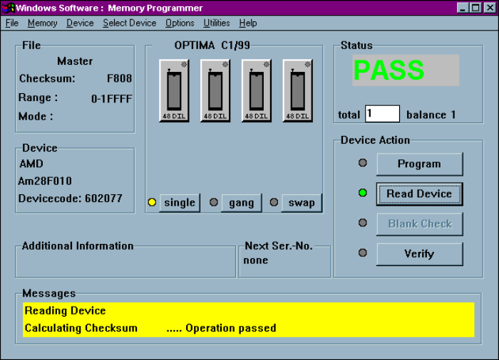
Device>Read
Selecting Device>Read retrieves the data contents of the device in the socket and
reads them into memory. While the read operation is in progress, the status window
displays the term ACTIVE and shows the percentage of completion. When the read
operation is complete, a PASS or FAIL message indicates its success or failure. Using
the <Read Device> button in the Device Action section yields the same results. Any
additional information related to this read operation is also displayed in the Messages
section of the screen:
Successful completion of a READ operation
When using a Multisyte programmer, insert the device in the left-most TOP for the
read operation.