OptimaUserManual.pdf - 第143页
SET PRO GRAM MING ON T HE TO P432 Opti ma User M anual 137 TOP432s installed on the programm er. In this mode, all devi ces inserted into all of th e T OP s will r eceiv e the same prog ra mming inf or mat ion . The TOP …
SET PROGRAMMING ON THE TOP432
Optima User Manual
136
SET PROGRAMMING ON THE TOP432
The TOP432 consists of four 32-pin sockets, and is designed primarily for gang
programming of memory devices, though it can also be used for set programming (up
to four devices) of memory devices. A limited range of logic devices can also be
programmed using the TOP432.
A Quad programmer with a TOP432 installed in Site #3
As with all TOPs, the TOP432 operates independently of other TOPs when different
TOP styles are installed on a Multisyte programmer. The only operating difference
between the TOP432 and other TOPs is the number of devices supported by each.
Otherwise all TOPs operate seamlessly on the programmer.
Like other TOPs, the TOP432 may be used in gang with other TOP432s on the same
programmer, thus providing a large throughput of devices. Using the TOP432 in a
multiple-gang capacity is as simple as choosing the gang selection and choosing all
SET PROGRAMMING ON THE TOP432
Optima User Manual
137
TOP432s installed on the programmer. In this mode, all devices inserted into all of
the TOPs will receive the same programming information.
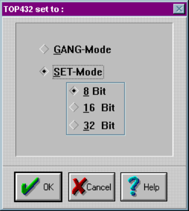
The TOP432 is unique because it has both gang and set programming capabilities. By
default the TOP432 is in the gang programming mode, where each device is
programmed with the same data. If you want to change to set programming, click on
the TOP432 icon. When the TOP432 icon appears, select SET-Mode programming.
In set mode, you have the option of 8, 16 or 32 bit programming mode:
Gang/Set mode screen

SET PROGRAMMING ON THE TOP432
Optima User Manual
138
8 Bit Mode
Select the 8 Bit mode when a large data file needs to be programmed over multiple
memory devices. In the example below the 64K file data is programmed into four
16K memory devices. The first 16K (0000-3FFF) is programmed into socket 1, the
second 16K (4000-7FFF) into socket 2, the third 16K (8000-BFFF) into socket 3, and
the fourth 16K (C000-FFFF) into socket 4.
The TOP432 creates the division of data automatically. The file is downloaded, the 8
Bit mode is selected and the programming operation is started.
Device Size Socket 1 Socket 2 Socket 3
Socket 4
27C64 0, 1, 2… 2000, 2001… 4000, 4001… 6000, 6001…
27C128 0, 1, 2… 4000, 4001… 8000, 8001… C000, C001…
16 Bit Mode
Select the 16 Bit mode when a 16 Bit data file needs to programmed into two 8 Bit
devices. In the example below the file data is a 16 Bit format. As the file data is read
during the programming operation, the TOP432 software places the low order bytes in
sockets 1 and 3. The high order bytes are placed in sockets 2 and 4.
Note: Often low order bytes are referred to as EVEN bytes and high
order bytes as ODD bytes.
The TOP432 creates the division of data automatically. The file is downloaded, the 16
Bit mode is selected and the programming operation is started.
Device Size Socket 1 Socket 2 Socket 3
Socket 4
27C64 0, 2, 4… 1, 3, 5… 4000, 4002… 4001, 4003…
27C128 0, 2, 4… 1, 3, 5… 8000, 8002… 8001, 8003…