OptimaUserManual.pdf - 第87页
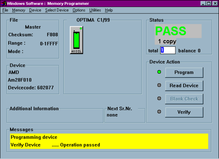
OPTIMA PROM SOF TW AR E Opti ma User M anual 81 Upon successful com pletion of the progra mming operation, P AS S will appear in th e Stat us ar ea ind ica tin g pro pe r p ro grammin g: Program ming operation has passed…
OPTIMA PROM SOFTWARE
Optima User Manual
80
Device>
Program
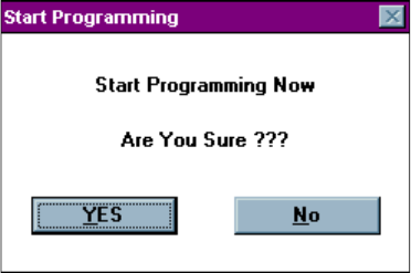
Selecting Device>Program produces the following dialogue:
Starting the Program routine
Selecting <Yes> begins the programming operation; <No> stops the programming
operation.
OPTIMA PROM SOFTWARE
Optima User Manual
81
Upon successful completion of the programming operation, PASS will appear in the
Status area indicating proper programming:
Programming operation has passed
Any special information related to the programming operation will appear in the
Messages text area at the bottom of the screen.
The first process performed on the device during the Program operation is a check for
blank state. If the device is EEPROM based, then an erase cycle will be executed
automatically. If it is not erased and is UV-erasable or is a one-time programmable
(OTP) device, the Optima software will test to see if the pattern in memory can be
over-programmed (that is, new data is programmed on top of the existing pattern in
the device). If over-programming is possible, then you will be asked Skip blank check:
Yes/No. If you select <YES>, then the device will be over-programmed. If you select
<No>, you will receive a “Device not blank” error message, and the Program
operation will stop.
OPTIMA PROM SOFTWARE
Optima User Manual
82
After the automatic blank check is completed, the device will then be programmed
using the algorithm defined by the manufacturer. Intelligent programming is used to
keep programming time to a minimum. The intelligent programming algorithm is
selected automatically when the device type is selected.
After programming, the device will be verified to confirm proper programming. If
there are any errors in verification, you can create a detailed report of the errors on the
screen (see Device>Verify section). If the device vendor specifies it, verification will
be done at the V
cc
high and V
cc
low levels in accordance with manufacturer’s
specifications.
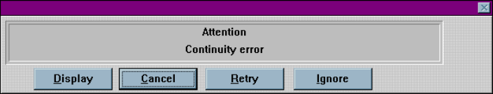
If the device is improperly inserted into the socket, the device is defective, or the
programming TOP is faulty, then a continuity message appears:
Continuity error
A yellow light on the TOP itself, as well as a yellow light on the TOP icon on the
Main Programming screen, identifies the socket with the continuity error. The
software prompts you to <Display> the pin(s) in error, <Cancel> the operation,
<Retry> the operation, or <Ignore> the error and continue.