OptimaUserManual.pdf - 第116页
OPT IMA PAL SO FTW ARE Opti ma User M anual 110 The Device M enu Th e t hir d me nu on t he Ma in P r ogr amming s cr ee n is th e Dev ic e menu. This menu is used to select the programm er operation for the device inser…

OPTIMA PAL SOFTWARE
Optima User Manual
109
x Page (upper button)—Moves the cursor up one page of data each time the
button is pressed
x Page (lower button)—Moves the cursor down one page of data each time the
button is pressed
x Up—Moves the cursor up one line of data each time the button is pressed
x Down—Moves the cursor down one line of data each time the button is pressed
An additional function that can be used from the editor screen is a simple fuse
location indicator. To use this indicator, simply place the mouse cursor over the
location in question, right-click the location with the mouse, and a window will appear
with the fuse location:
Right-clicking the edit screen will provide the fuse location under the cursor
OPTIMA PAL SOFTWARE
Optima User Manual
110
The Device Menu
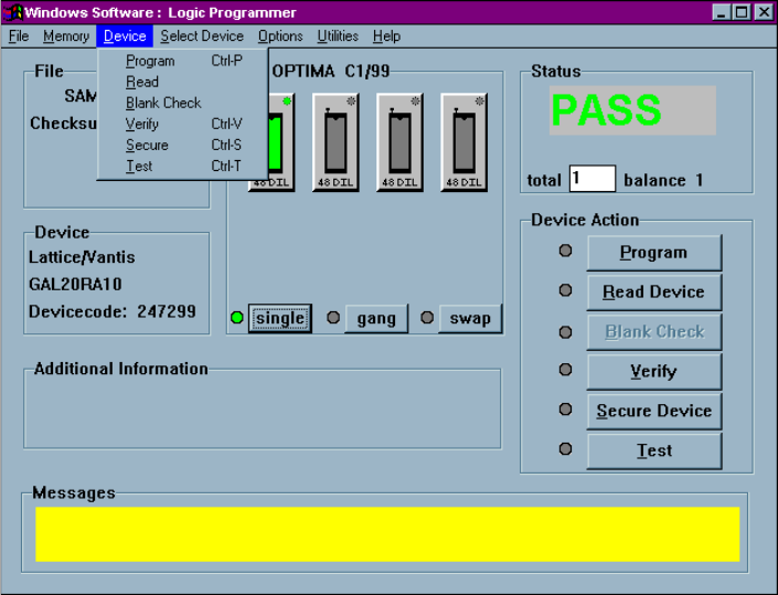
The third menu on the Main Programming screen is the Device menu. This menu is
used to select the programmer operation for the device inserted:
The Device menu
Device> Program
This selection initiates the programming operation using the data that is stored in the
memory buffer. The device type selected must match the physical device in the
socket.
The device will first be checked for blank state or electrically erased. If the device is
electrically erasable, then an erase cycle will be automatically executed. If it is not
erased—and is UV-erasable or is a one-time-programmable (OTP) device—the PAL
OPTIMA PAL SOFTWARE
Optima User Manual
111
software will test to see if the pattern in memory can be over-programmed, where
additional data is programmed on top of the existing pattern in the device. If over-
programming is possible, then you will be prompted to “Skip blank check.” If you
select <Yes>, then the device will be over-programmed. If you select <No>, you will
receive a “Device not blank” error, and programming will stop.
After the blank check or erase operation is complete, the device will be programmed
using the algorithm defined by the manufacturer.
After programming, the device will be verified to confirm proper programming. If
there are any errors in verification, you can create a detailed report of the errors on the
screen (see Device>Verify later in this menu description). If the device vendor
specifies it, verification will be done at the V
CC
high and V
CC
low levels in accordance
with manufacturer’s specifications. After verification, if the security fuse command
was included in the JEDEC file, the security fuse of the device will be set (see
Device>Secure later in this menu description). If test vectors were included in the
JEDEC file, they will then be used to exercise the device (see Device>Test later in
this menu description).
You are informed of the sequence of steps in the programming operation by messages
on the screen. PASS/FAIL messages are provided in the status box indicating
programming status. A cycle counter is provided below the PASS/FAIL message area
displaying the number of devices programmed with the same content.