ALFeeder_E.pdf - 第101页
3. Maintenance / Replacing procedure 4-13 Chapter 4 Maintenance and parts replacement 3.5.2 Replacing tail pin ► Attaching tail pin using jig Using a tail pin attachment jig (KHJ-ME101-00X JIG, T AIL PIN) is recommended.…
3. Maintenance / Replacing procedure
4-12
Chapter 4 Maintenance and parts replacement
3.5 Clamp section
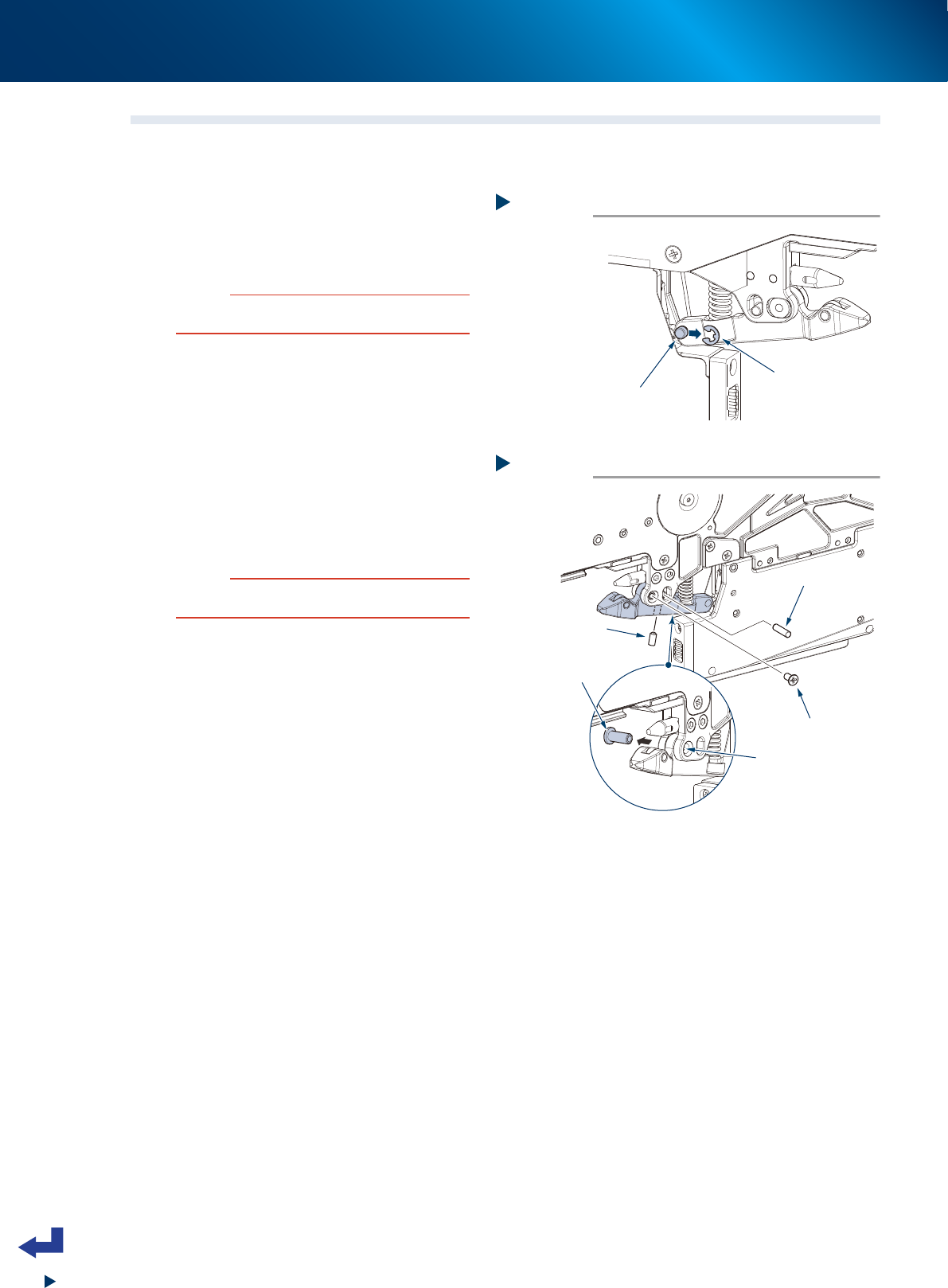
3.5.1 Replacing clamp lever assembly
1
Detach shaft for unclamp wire.
1. Detach E-ring for unclamp wire with
flat-head precision screwdriver.
2. Detach shaft for unclamp wire.
c
CAUTION
• Make sure not to lose E-ring when detaching it.
• Do not use any E-ring other than specified.
2
Detach clamp pin.
1. Remove 1 screw mounting clamp lever
assembly with Phillips screwdriver.
2. Push out clamp pin by inserting hex wrench,
etc. in screw hole.
3
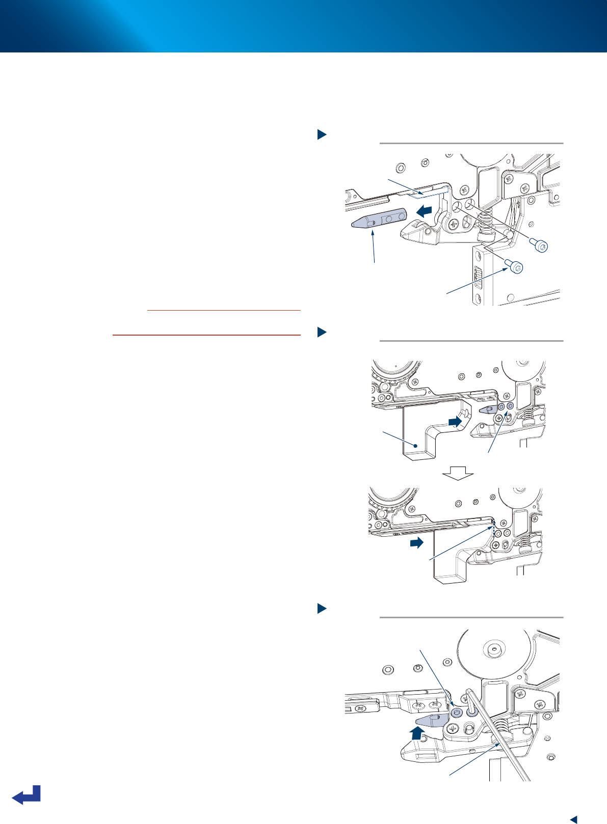
Detach torque limiter pin.
Loosen 1 setscrew with hex wrench (1.5) and
pull out torque limiter pin.
4
Detach clamp lever assembly.
c
CAUTION
Make sure not to lose spring when detaching clamp lever
assembly.
5
Attach clamp lever assembly.
Attach clamp lever assembly to be replaced in
reverse order of Step 1 to Step 3.
Step 1
Detaching E-ring
E-ring
Shaft for unclamp wire
63412-KLU-30
Step 2, 3
Detaching clamp lever assembly
Torque limiter pin
Clamp pin
Push out clamp pin
with hex wrench, etc.
Screw
Setscrew
63413-KLU-30
3. Maintenance / Replacing procedure
4-13
Chapter 4 Maintenance and parts replacement
3.5.2 Replacing tail pin
►
Attaching tail pin using jig
Using a tail pin attachment jig (KHJ-ME101-00X JIG, TAIL PIN) is recommended.
1
Detach tail pin.
Remove 2 bolts mounting tail pin with hex
wrench (2.5) and pull out tail pin from feeder
body.
2
Attach tail pin to be replaced.
1. Install 2 bolts temporarily with hex wrench
(2.5) to attach tail pin to be replaced to
feeder body.
2. Open clamp lever assembly and set tail pin
attachment jig.
3. Tighten 2 bolts for tail pin fully with hex
wrench (2.5).
• Tightening torque: 55 N·cm
c
CAUTION
Attaching tail pin obliquely may make feeder difficult to
attach/detach.
►
Attaching tail pin without jig
When tightening 2 bolts for tail pin fully, press
tail pin in arrow's direction shown in the figure
on the right.
Step 1
Detaching tail pin
Tail pin
Mounting bolts
Under plate
63416-KLU-30
Step 2
Attaching tail pin
Bolts mounted
temporarily
Jig touches here
Tail pin
attachment jig
63417-KLU-30
Attaching tail pin without jig
Bolts mounted temporarily
Push tail pin in
arrow’s direction.
Hex wrench
63418-KLU-30
3. Maintenance / Replacing procedure
4-14
Chapter 4 Maintenance and parts replacement
3.6 Electrical connecting section
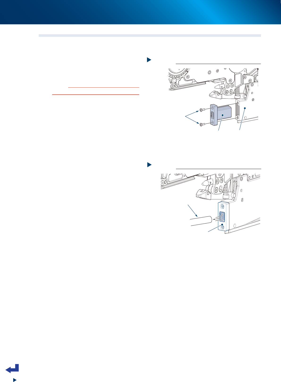
3.6.1 Replacing board connector
1
Detach board connector.
1. Remove 2 screws mounting board connector
to EL box with Phillips screwdriver.
2. Pull out board connector forward.
c
CAUTION
Do not touch terminal inside of board connector.
2
Attach board connector.
1. Align new board connector with EL box
mounting groove and insert it.
2. Apply thread lock (LOCTITE 241) to 2
screws an tighten them with Phillips
screwdriver.
• Tightening torque: 30 N·cm
►
Clean board connector.
Remove dust and dirt with vacuum tool (option)
or small vacuum cleaner.
Step 1
Detaching board connector
Screw
EL box
Board connector
63419-KLU-30
Cleaning board connector
Board connector
Vacuum tool or
small vacuum cleaner
63420-KLU-30