ALFeeder_E.pdf - 第70页
2. Preaparation for operation 3-24 Chapter 3 Setting up █ Procedur e for setting up component tape with IT Option 1 Prepare comp onent ta pe to be set. 1. Select the [Monitor] - [Production] screen. 2. Check the componen…
2. Preaparation for operation
3-23
Chapter 3 Setting up
2.2.2 Setting up component tape with IT Option
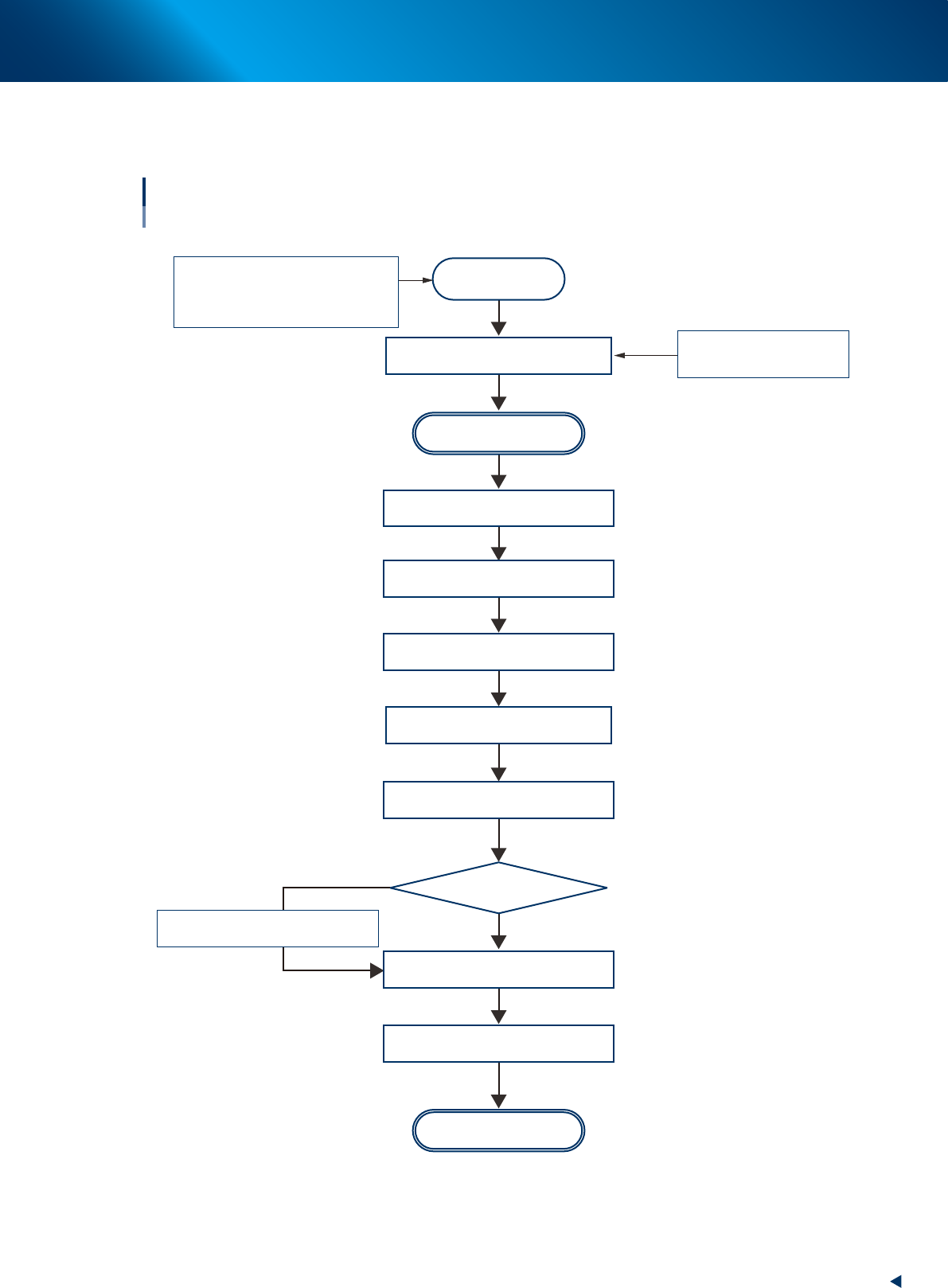
The following describes the flowchart of setting component tape with IT Option.
Start operation
Flowchart of setting up component tape
With IT Option
LEDs flash continuously
Preparation
Scan component ID
No
Yes
Newly set ?
Set component tape to be added
to loading unit
Check setting status
Cut/Fold top of compontnent tape
Start setting
Prepare reel
On [Monitor] - [Production] screen
新テープを
Set component tape newly
Auto Loading Feeder capability list
Auto Loading Feeder Optimizer
Setup Assignment
Prepare Auto Loading Feeder
Set Auto Loading Feeder
Check [Monitor] - [Production]
screen or setup list
Set reel
Set component tape newly or
supply component tape
Set component tape newly
Set preset holder
Move down component tape in operation
63321-KLU-30
2. Preaparation for operation
3-24
Chapter 3 Setting up
█
Procedure for setting up component tape with IT Option
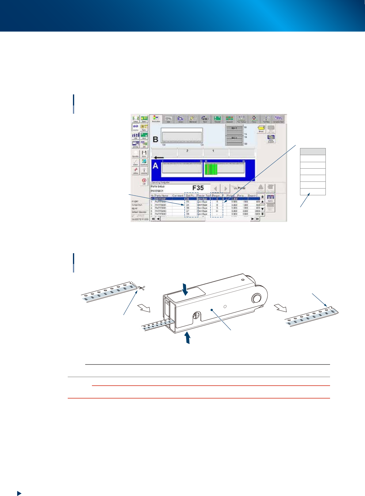
1
Prepare component tape to be set.
1. Select the [Monitor] - [Production] screen.
2. Check the component name and set position in "Operating Navigation" box, and tape guide
type in the Request column of Parts list.
Operating Navigation box
Tape guide type
Parts name,
Feeder set position
Auto Loading Feeder
is not used.
Request size
LL
L
M
S
2S
-
64301-KLU-40
2
Cutting/Folding top of component tape.
Cutting/Folding top of component tape
Cut from pocket side.
Check folded position.
Tape leveler
Insert component tape and
grip top and bottom of tape leveler.
63302-KLU-40
n
NOTE
See "1.2 Folding top of component tape"in chapter 2 for more detail.
c
CAUTION
Make sure to cut and fold the top of component tape correctly. Otherwise component tape may not be loaded.
2. Preaparation for operation
3-25
Chapter 3 Setting up
3
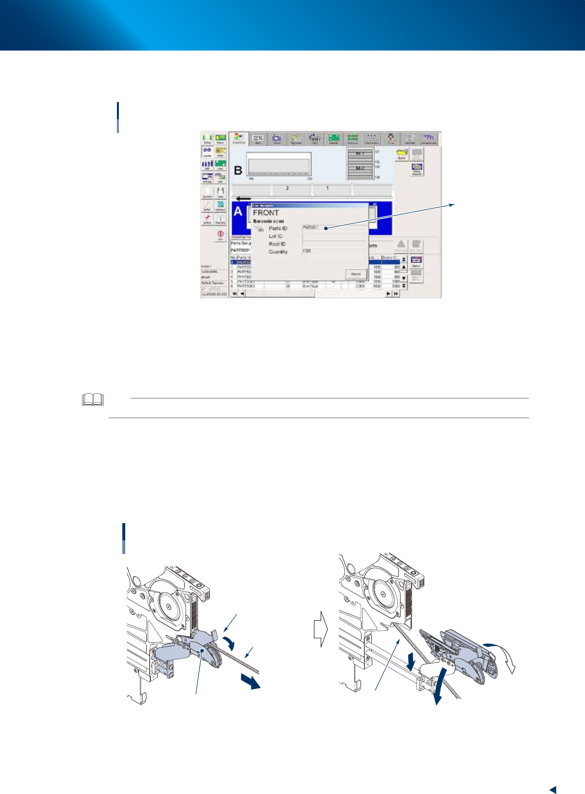
Scan the component tape (reel) ID.
Scan the ID of component tape (reel) to be added with bar code reader.
Scanning component tape (reel) ID
Set position is specified
by this ID.
64308-KLU-30
4
Set Auto loading feeder.
The reel scanned in Step 3 is specified and LEDs on feeder flash continuously.
1. Set Auto loading feeder to the feeder set position where LEDs flash continuously.
2. Set preset holder to feeder exchange carriage or reel holder for feeder bank.
TIP
See Step3 of "2.2.1 Setting up component tape without IT Option" for preset holder setting procedure.
5
Set a tape reel, to be added newly or to be supplied, to preset holder.
6
Set the component tape to the loading unit.
1. While pressing down the tape clamp lever and pull the loading unit to front end.
2. (If the 1st reel spplies components) the clamp unit opens left and right by releasing the tape
clamp lever, the component tape in operation is fallen down below the loading unit.
Pulling out loading unit
Moving down the component tape in operation
Clamp unit opens
by releasing tape clamp lever
Tape clamp lever
Loading unit
Tape component
in operation
Tape component
in operation
63331-KLU-00