ALFeeder_E.pdf - 第21页
1. Overview 1-9 Chapter 1 Overview 1.4 Selecting Auto loading feeder with special jig 1.4.1 Cover tape checker (for checking the seal of cover tape and pocket size) Selecting Auto loading feeder and judging the a vailabi…
1. Overview
1-8
Chapter 1 Overview
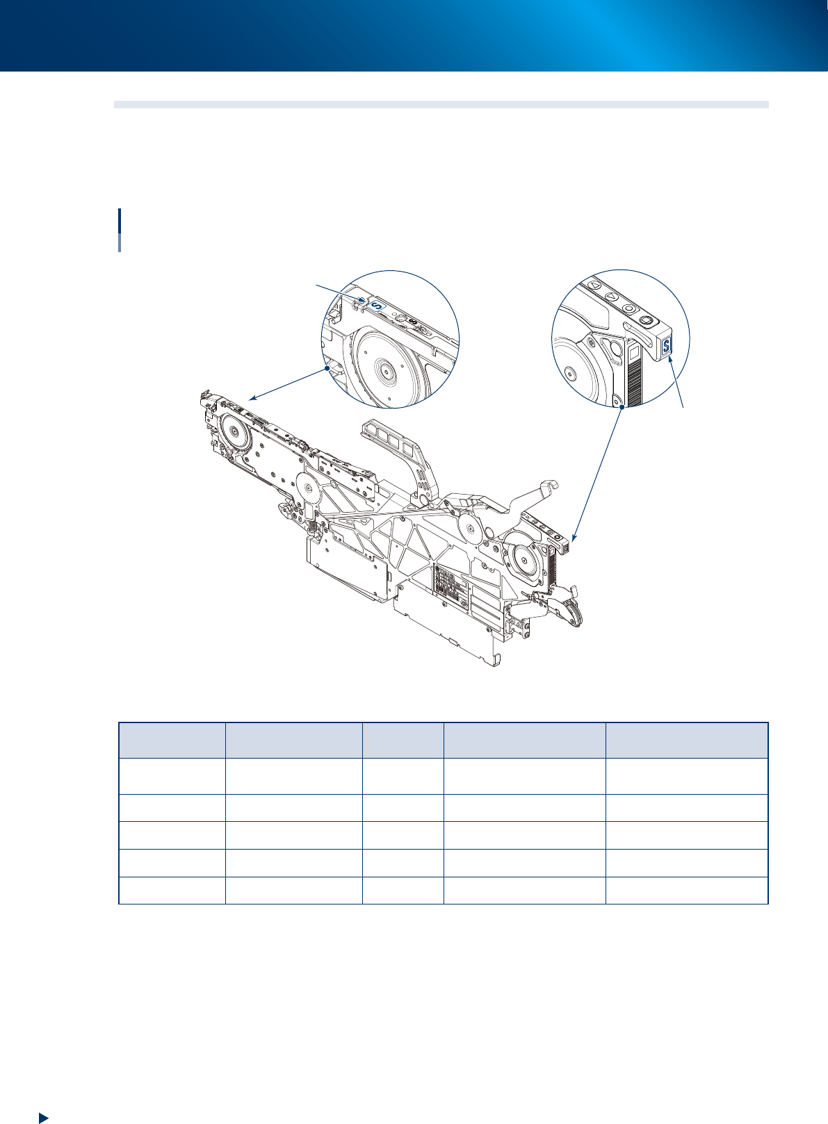
1.3 Types of Auto loading feeder and available component size
Auto loading feeder is classified according to the available component size shown in the table below. Make
sure to check the type displays on tape guide and operation panel shown in the figure below. Additionally,
use the special jig (cover tape checker) to select Auto loading feeder available for the component tape to be
used.
Types of Auto loading feeder
Type display positions
Tape guide
Operation panel
Type display
Type display
63100-KLU-40
Available component size: Unit is mm. Figures in ( ) are sizes in inches.
Type display/
Engraving
Available
component size
Tape Tape width Feed pitch (mm)
2S
0603 (0201)* / 1005
(0402)
Paper 8mm 2mm
S 1005 (0402) Paper 8mm 2mm
M 1608 (0603) Paper 8mm 2mm or 4mm
L 2012 (0805) Paper 8mm 2mm or 4mm
LL 3216 (1206) Paper 8mm 2mm or 4mm
*0603(0201) size supports only magnetic components.
1. Overview
1-9
Chapter 1 Overview
1.4 Selecting Auto loading feeder with special jig
1.4.1
Cover tape checker (for checking the seal of cover tape and pocket size)
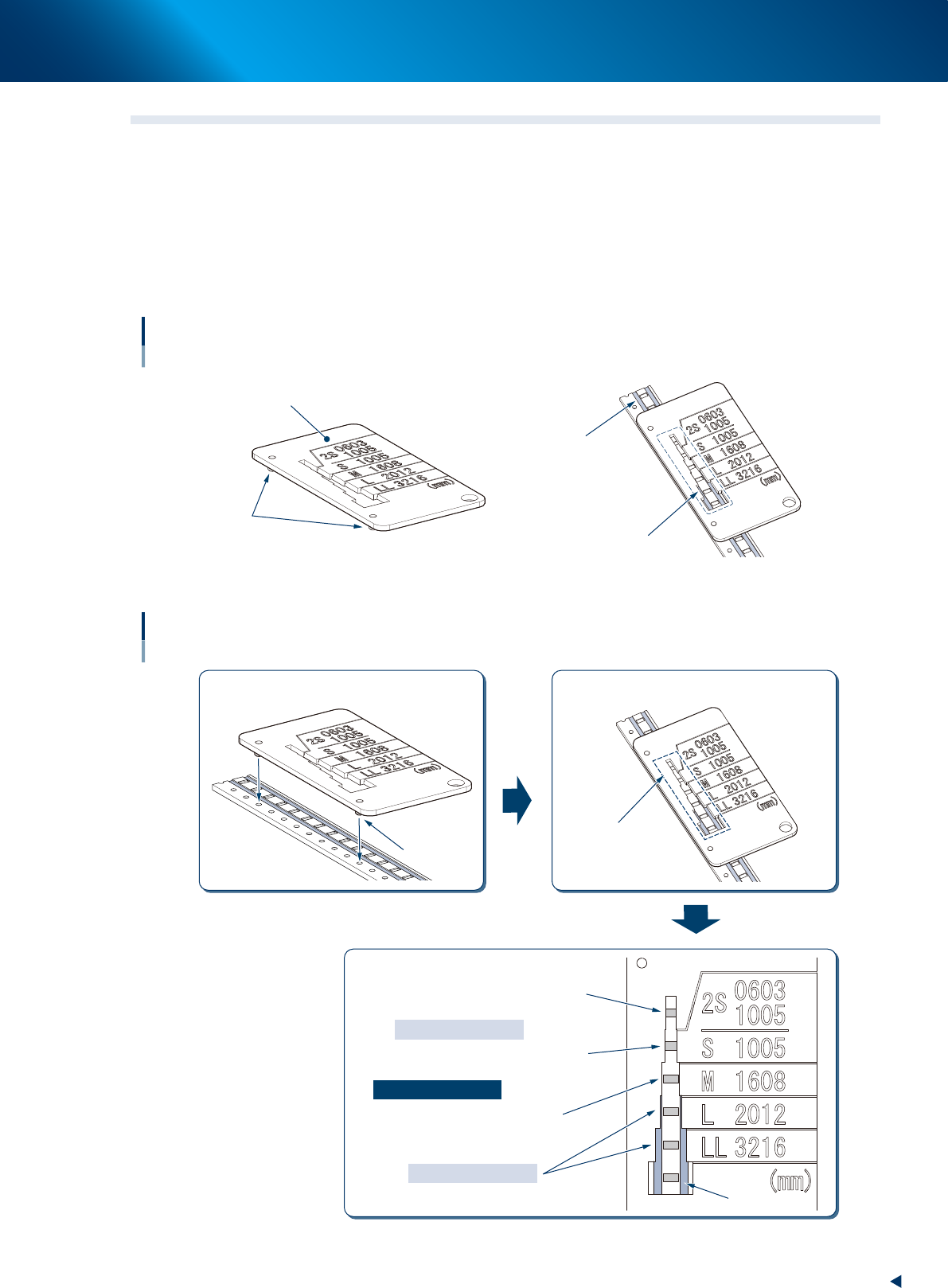
Selecting Auto loading feeder and judging the availability by checking the seal of cover tape and pocket size
with the special jig. The following is the availability conditions.
• The edge of the component pocket can be seen from the window for checking seal width.
• The seal cannot be seen from the window for checking seal width.
• The clearance is applied between the seals on left and right, and cover tape checker.
Cover tape checker
Jig for checking seal width
Cover tape checker
Locating pin
Seal
Window for
checking seal width
63109-KLU-50
Using cover tape checker
1
3
2
Locate pin
Window for
checking seal width
Insert locating pins into feed holes.
Checking through window for checking
seal width.
Determining targeted size.
Reason of inapplicable
Reason of applicable
Reason of inapplicable
The edge of component pocket
cannot be seen.
The edge of component pocket
can be seen, but the seal cannot be seen.
The seal can be seen.
Inapplicable
Inapplicable
63113-KLU-10
1. Overview
1-10
Chapter 1 Overview
1.4.2 Tape cut jig / Tape leveler
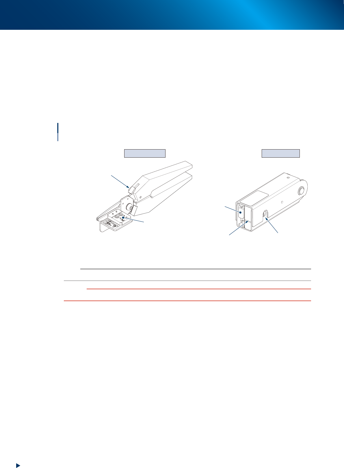
The top of the component tape must be folded in advance to load a component tape correctly after cutting a
component tape with tape cut jig (scissors). Fold the top of component tape with tape leveler.
►
Tape cut jig (scissors)
Used to cut for cutting/folding top of component tape. The component tape is cut correctly by setting it
to prescribed position, and this jig is available for the cut position of both 2mm pitch and 4mm pitch.
►
Tape leveler (folding top of component tape jig)
Used to fold the top of component tape. The folding position can be checked through the window to
check folding position placed at side.
Tape cut jig Tape leveler
Tape cut jig / Tape leveler
Cutting component tape / Folding top of component tape
Insertion position
of component tape (paper)
Window to check
folding position
Do not use this side.
Locking lever
Tape set position
63110-KLU-10
n
NOTE
See Ch. 2 "1.1 Cutting component tape" to use the tape cut jig/tape leveler.
c
CAUTION
Make sure to cut and fold the top of component tape correctly. Otherwise component tape may not be loaded.