ALFeeder_E.pdf - 第76页
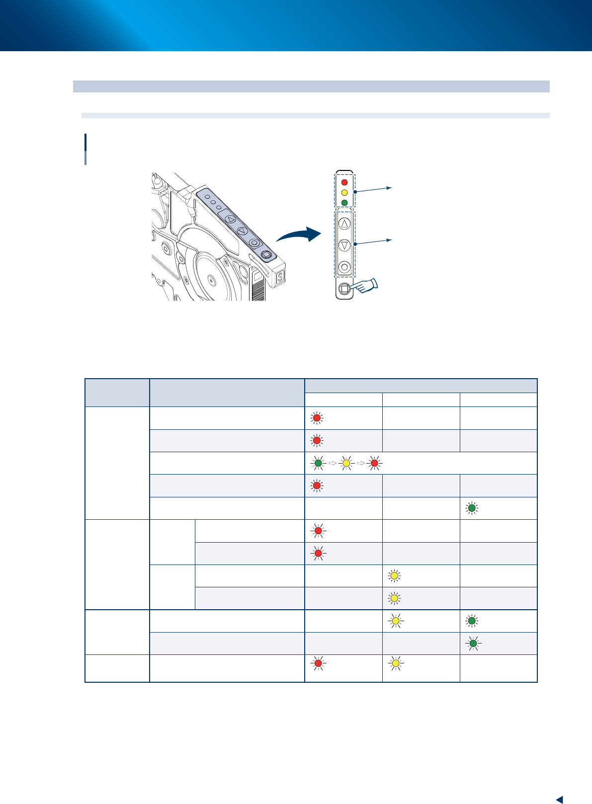
3. Operation panel 3-30 Chapter 3 Setting up 3.1.2 Buttons on operation panel ► The [FEED] button The [FEED] button feeds component tape to the pickup position. The continuous feed is available by keep pressing the [FEED…
3. Operation panel
3-29
Chapter 3 Setting up
3. Operation panel
3.1 Buttons on operation panel and LEDs
LED1
LED2
LED3
FEED
BACK
FUNC
LOAD
LED1
LED2
LED3
FEED
BACK
FUNC
LOAD
Buttons on operation panel and LEDs
LEDs
Operation buttons
[LOAD] button
63310-KLU-30
3.1.1 LED lighting patterns/Status
The lighting status of the LED display on the operation panel is shown below. "Setup change" and "Out of
components" of feeder are indicated.
Status Detail
LED
LED1 (Red) LED2 (Yellow) LED3 (Green)
Setup change
No setup (Removal command)
Light up
Wrong setup
Light up
Setup position indication
Continuous flash
Normal component set reliability NG*
Light up
Setup completion set position
Light up
Out of
components
Stop due to
remaining
amount
Stop due to remaining amount
(out of components)
Flash
Changing to alternative
components
Flash
Retry over
Pickup/recognition error stop
Light up
Changing to alternative
components
Light up
Component
shortage
warning
Component shortage warning
Flash
Light up
Preset
Flash
Feeder error
Flash
(High-speed)
Flash
(High-speed)
*"Normal component set reliability NG" means the condition where normal component is set but cannot be used as the setup check is not performed yet.
3. Operation panel
3-30
Chapter 3 Setting up
3.1.2 Buttons on operation panel
►
The [FEED] button
The [FEED] button feeds component tape to the pickup position. The continuous feed is available by
keep pressing the [FEED] button.
►
The [BACK] button
The [BACK] button is used with the [FUNC] button.
►
The [FUNC] button
The [FUNC] button is used with the [FEED] button or [BACK] button.
[FUNC]+[FEED]: Ejects component tape forcibly from the front side of feeder.
[FUNC]+[BACK]: Unloads component tape to the rear of feeder.
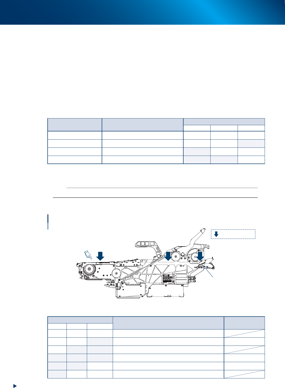
Feeder operation/Sensor detection status
Button operation Feeder operation
Tape detection status (sensor)
1 (Top) 2 (Center) 3 (Entrance)
[FEED]: Press once Feed 1 pitch (2 mm). No care No care No care
[LOAD]: Press once Feed component tape to pickup position OFF OFF ON
[FUNC]+[FEED]: Press once Eject component tape from front. ON No care No care
[FUNC]+[BACK]: Press once Eject component tape from rear. ON ON OFF
►
[LOAD] button
Feeds the preset component tape to the pickup position.
n
NOTE
The button operations above are not activated during automatic operation.
3.1.3 Sensors inside of the feeder body
1
2 3
Position of tape detection sensor
: Tape detection sensor
Loading unit
Pickup position
63311-KLU-40
Sensor detection status/Available operation
Sensor No.
Status Available operation
1 (Top) 2 (Center) 3 (Entrance)
OFF OFF OFF All sensors do not detect component tape.
OFF OFF ON Sensor 3 detects component tape to be added. Load
OFF ON ON Component tape to be added is being loaded to pick up position.
ON ON ON All sensors detect component tape. Pickup
ON ON OFF Sensor 1 and 2 detect component tape. Pickup/Unload
ON OFF No care Sensor 1 only detects component tape (end of tape component).
3. Operation panel
3-31
Chapter 3 Setting up
3.2 Single operation
The following describes the single operation of loading and unloading. The following operation is not
performed usually, as the used component tape that was in operation is ejected and the new component
tape is loaded automatically.
3.2.1 Loading component tape
The component tape to be added is fed into the feeder.
█
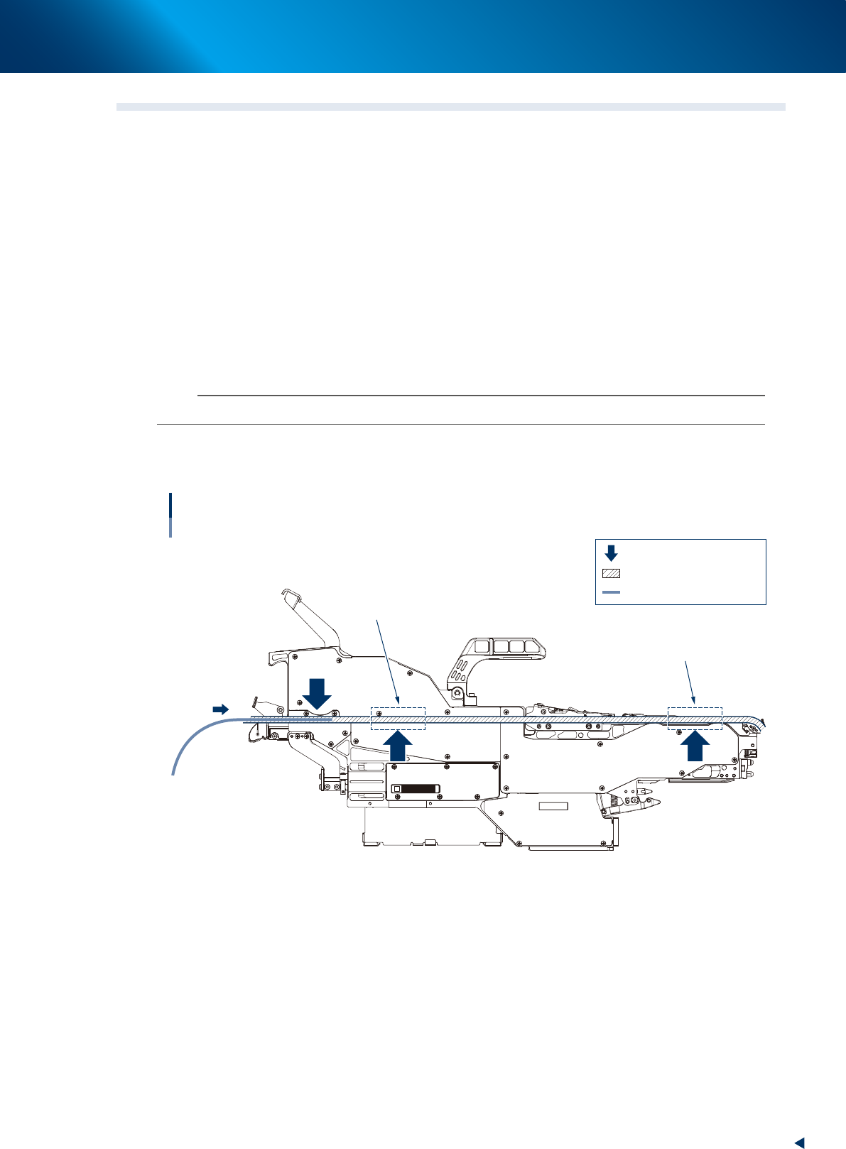
Operable conditions
• The component tape detection sensor 1 and 2 are OFF.
• No component tape is in the areas shown in the figure below.
1
Set the top of component tape.
Set the top of component tape to be added to the specific position on loading unit.
n
NOTE
See "2.2 Setting up component tape" for the procedure of tape setting.
2
Press the [LOAD] button.
The component tape is loaded. It is fed into the feeder. Then the setting is completed.
12
3
Loading component tape
: Component tape detection sensor
: Component tape path
: Component tape
No component tape must
not be in these areas.
No component tape must
not be in these areas.
63312-KLU-30