ALFeeder_E.pdf - 第104页
3. Maintenance / Replacing procedure 4-16 Chapter 4 Maintenance and parts replacement 3.8 Loading unit T here are two types of clamp units in the loading unit, revised and former , but the only revised type is shipped as…
3. Maintenance / Replacing procedure
4-15
Chapter 4 Maintenance and parts replacement
3.7 Operation section
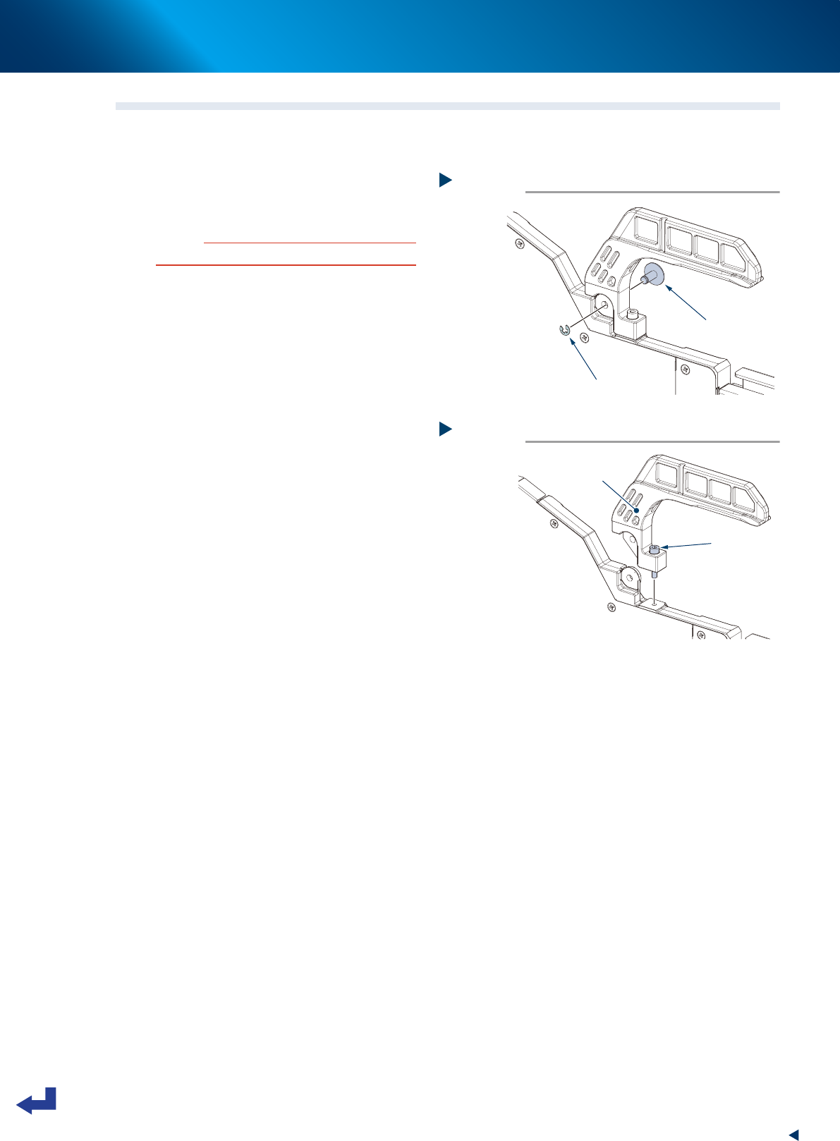
3.7.1 Replacing handle
1
Remove handle pin.
Detach E-ring for handle pin mounting handle
with precision screwdriver.
c
CAUTION
Make sure not to lose E-ring when detaching it.
2
Detach handle.
Loosen 1 bolt mounting handle with hex wrench
(2.5) to detach handle from feeder body.
3
Attach handle.
Attach handle in reverse order of Step 1 to
Step 2.
• Tightening torque: 100 N·cm
Step 2
Detaching handle
Mounting bolt
Handle
63422-KLU-30
Step 1
Removing handle pin
E-ring
Handle pin
63421-KLU-30
3. Maintenance / Replacing procedure
4-16
Chapter 4 Maintenance and parts replacement
3.8 Loading unit
There are two types of clamp units in the loading unit, revised and former, but the only revised type is
shipped as a replacement parts. Note that it cannot use left and right of former and revised clamp units
together. So that when the clamp unit of former type damages, both left and right parts of clamp units
should be replaced at the same time.
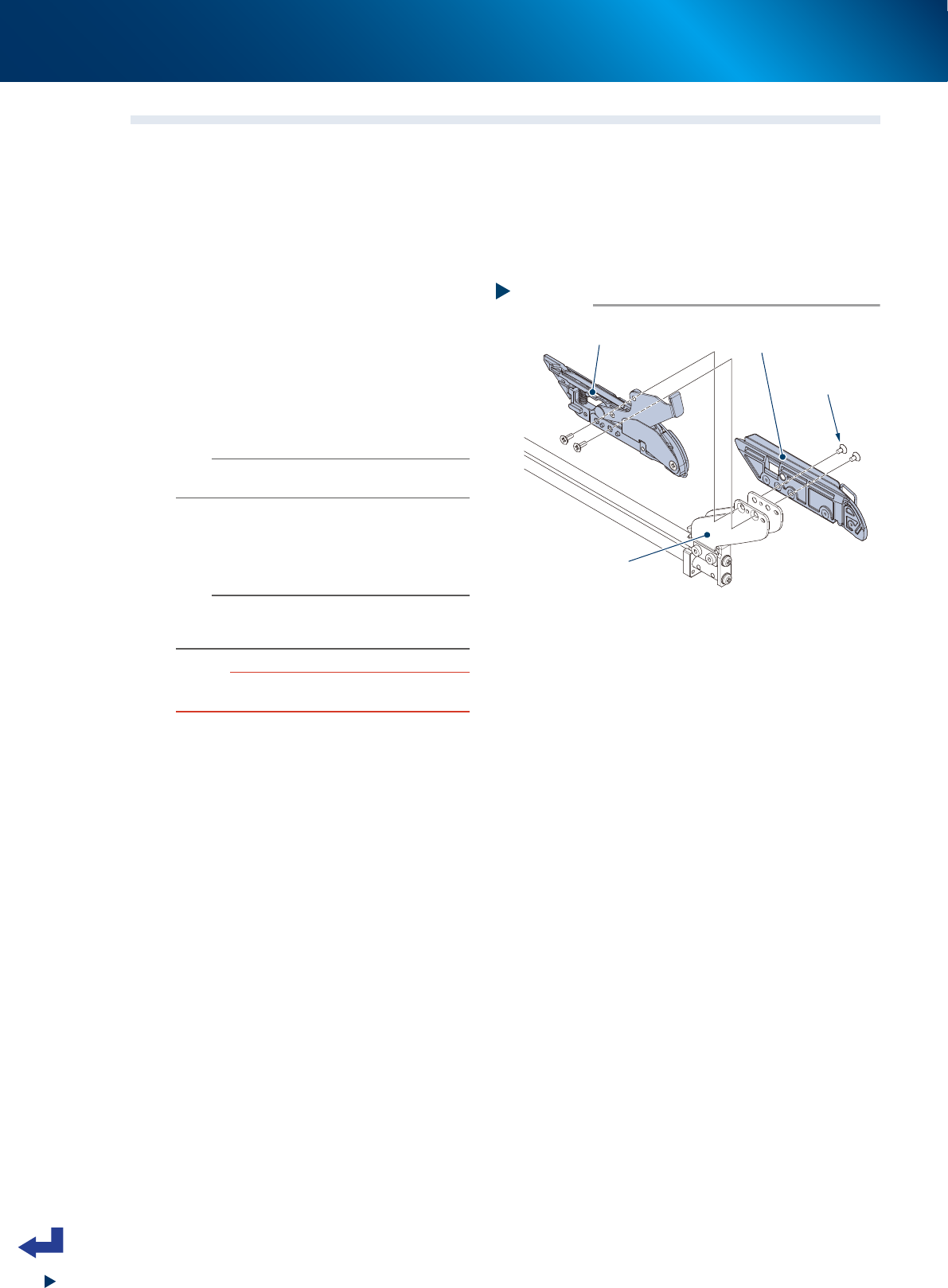
3.8.1 Replacing clamp units
1
Detach tape clamps.
Remove bolts mounting clamp units with Phillips
screwdriver.
2
Attach new clamp units.
Attach new clamp units in reverse order of Step
1.
• Tightening torque: 40 N·cm
n
NOTE
Make sure to replace both left and right clamp units as a
set.
3
Check the operation.
Check that loading unit can be inserted/
removed smoothly into/from feeder body.
n
NOTE
If loading unit cannot be inserted into feeder body
smoothly, loose mounting bolts and tighten them as a
minor adjustment.
c
CAUTION
Do not apply grease or turbine oil to the loading unit as
the plastic may deteriorates.
Step 1,2
Replacing clamp unit
Tape clamp bracket
Tape clamp 2
Mounting bolt
Tape clamp 1
63428-KLU-40
3. Maintenance / Replacing procedure
4-17
Chapter 4 Maintenance and parts replacement
3.9 Preset holder section
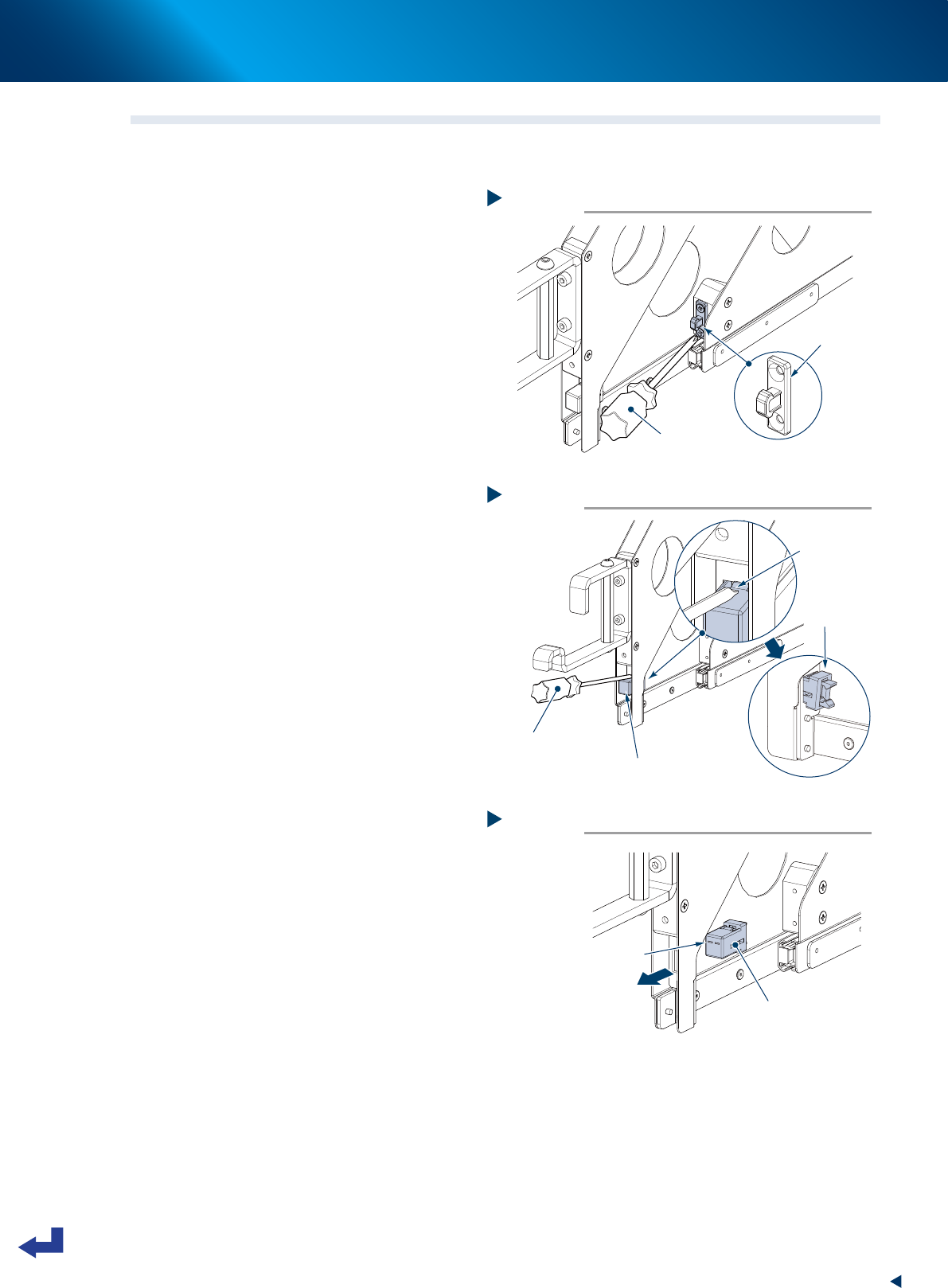
3.9.1 Replacing sliding stopper
1
Replace keeper on sliding side.
Detach keeper on sliding section with Phillips
screwdriver. Then attach new keeper.
2
Detach stopper main unit.
1. Press claw as shown at right with flat-head
screwdriver to move it inside.
2. Press the other side of claw to detach
stopper main unit from preset holder.
3
Attach stopper main unit.
Face up the surface with hole as shown at right.
Then Insert stopper main unit from inside.
4
Check the operation.
Press sliding section of preset holder to check
the operation of locking/unlocking.
Step 1
Replacing keeper
Phillips screwdriver
Keeper
63430-KLU-30
Step 2
Detaching stopper main unit
Flat-head screwdriver
Stopper main unit
Detaching crow.
(2 positions)
Pull out.
63431-KLU-30
Step 3
Attaching stopper main unit
Face up surface with hole.
Stopper main unit
63432-KLU-30