ALFeeder_E.pdf - 第64页
2. Preaparation for operation 3-18 Chapter 3 Setting up 2.2 Setting up component tape 2.2.1 Setting up component tape without IT Option T his section describes the procedure of setting the component tape without any opti…
2. Preaparation for operation
3-17
Chapter 3 Setting up
►
Set position of preset holder (YRM20 is excluded)
• When the tape reels for ZS/SS feeders are set to the upper reel holders, the positions of lower reel
holder need to be changed.
• When a feeder uses 13 inch or larger reeo, a preset holder cannot be attached to the lower reel
holders
n
NOTE
As to attaching YRM20 reel holder to lower row, it can basically be attached anywhere as the set position of preset holder
is not limited. Attach them where does not affect to tape flow.
►
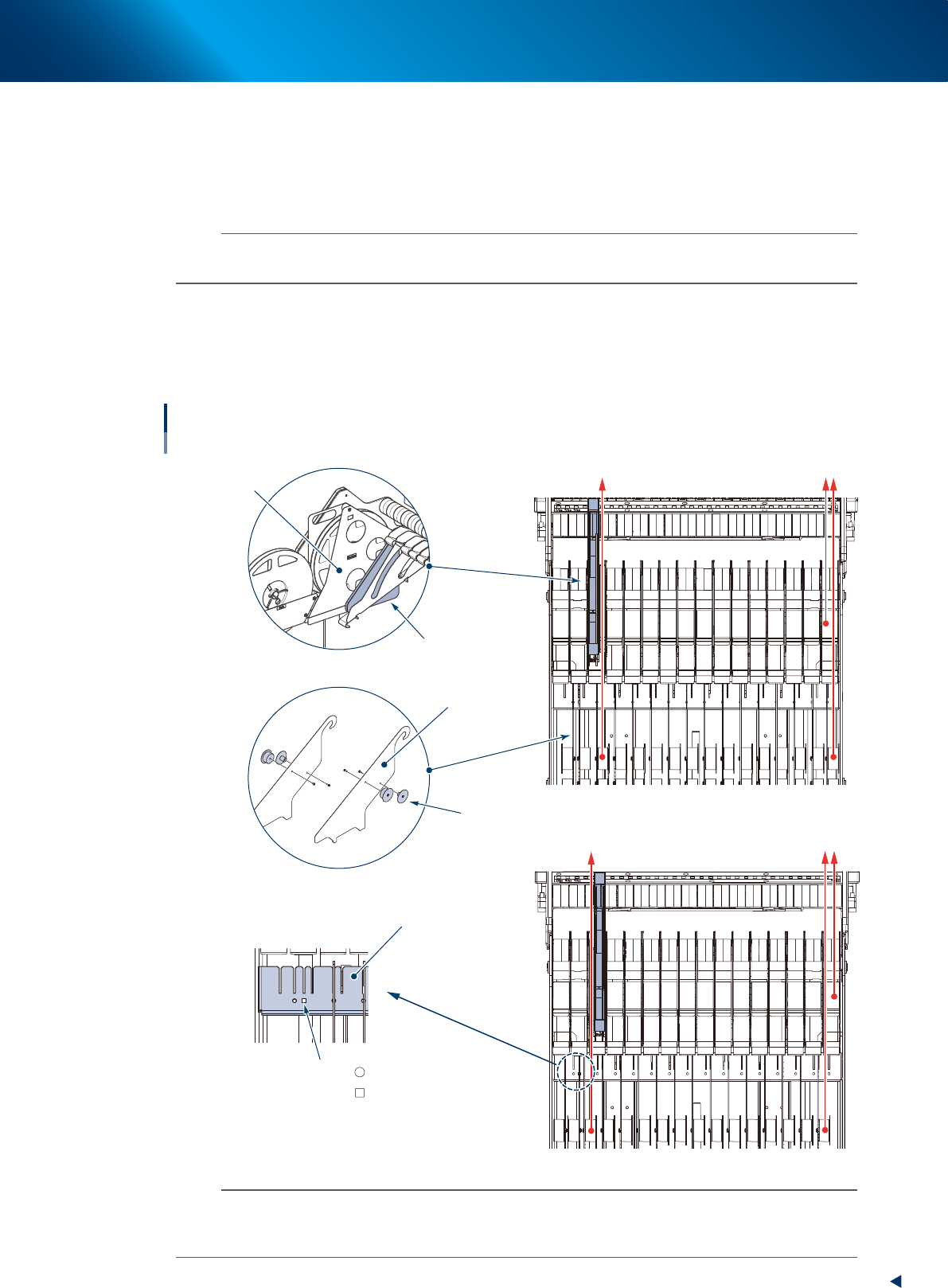
Partition setting procedure
1. If a preset holder is attached to upper row of carriage, check that it is left-sided or right-sided.
2. Check the mark on partition bracket. Set the partition for the tape path (red arrow below) to be
vertical.
Set position of partition
Left side/Right side
Reel holder pad
Preset holder
Partition
Boss
Example: Setting preset holder left side
Example: Setting preset holder right side
Partition bracket
Setting position of partition
Changing attachment position of boss
Mark : Left side
: Left or right side
No Mark : Right side
63327-KLU-30
n
NOTE
Setting preset holder left side: Set the boss on the left-most and square
mark partitions oppositely.
Setting preset holder right side: Set the boss on the left-most partition oppositely.
Moreover, the square mark (for left and right side) is not applied to the machine with reel holder for feeder bank.
2. Preaparation for operation
3-18
Chapter 3 Setting up
2.2 Setting up component tape
2.2.1 Setting up component tape without IT Option
This section describes the procedure of setting the component tape without any optional software (IT
option).
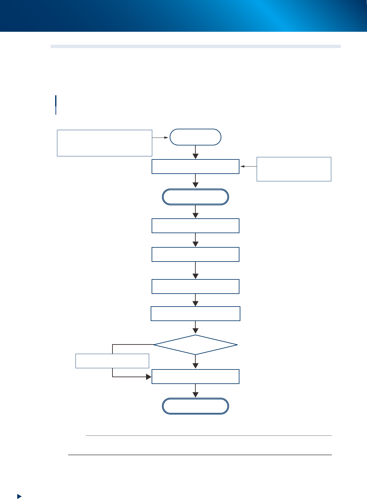
Flowchart of setting up component tape
Without IT Option
Preparation
Prepare component tape
Set the Auto loading feeder
Auto Loading Feeder capability list
Auto Loading Feeder Optimizer
Setup Assignment
Y.FacT (P-TOOL)
Cut/Fold top of component tape
Start setting
Set component tape newly or
supply component tape
Newly
Check the [Monitor] - [Production]
screen or the [Setup Assignment]
screen
Set component tape
Set preset holder
Set component tape newly or
supply component tape
Start operation
No
Yes
Newly set ?
Set component tape to be added
to loading position
Move down component tape
in operation from loading unit
63301-KLU-30
n
NOTE
The flowchart above is the setting component tape without IT Option. The procedure or instruction screen may differ if using
IT Option.
2. Preaparation for operation
3-19
Chapter 3 Setting up
█
Procedure for setting up component tape without IT Option
The following procedure assumes that setting Auto Loading Feeder Capability list, performing Auto
loading feeder Optimizer, Setup Assignment are completed and Auto loading feeders are placed.
c
CAUTION
Check that tape guide type matches with Auto loading feeder size before setting Auto loading feeder on the feeder bank.
Additionally, remove a tape if it is pinched in dicharge assembly on top of tape guide section.
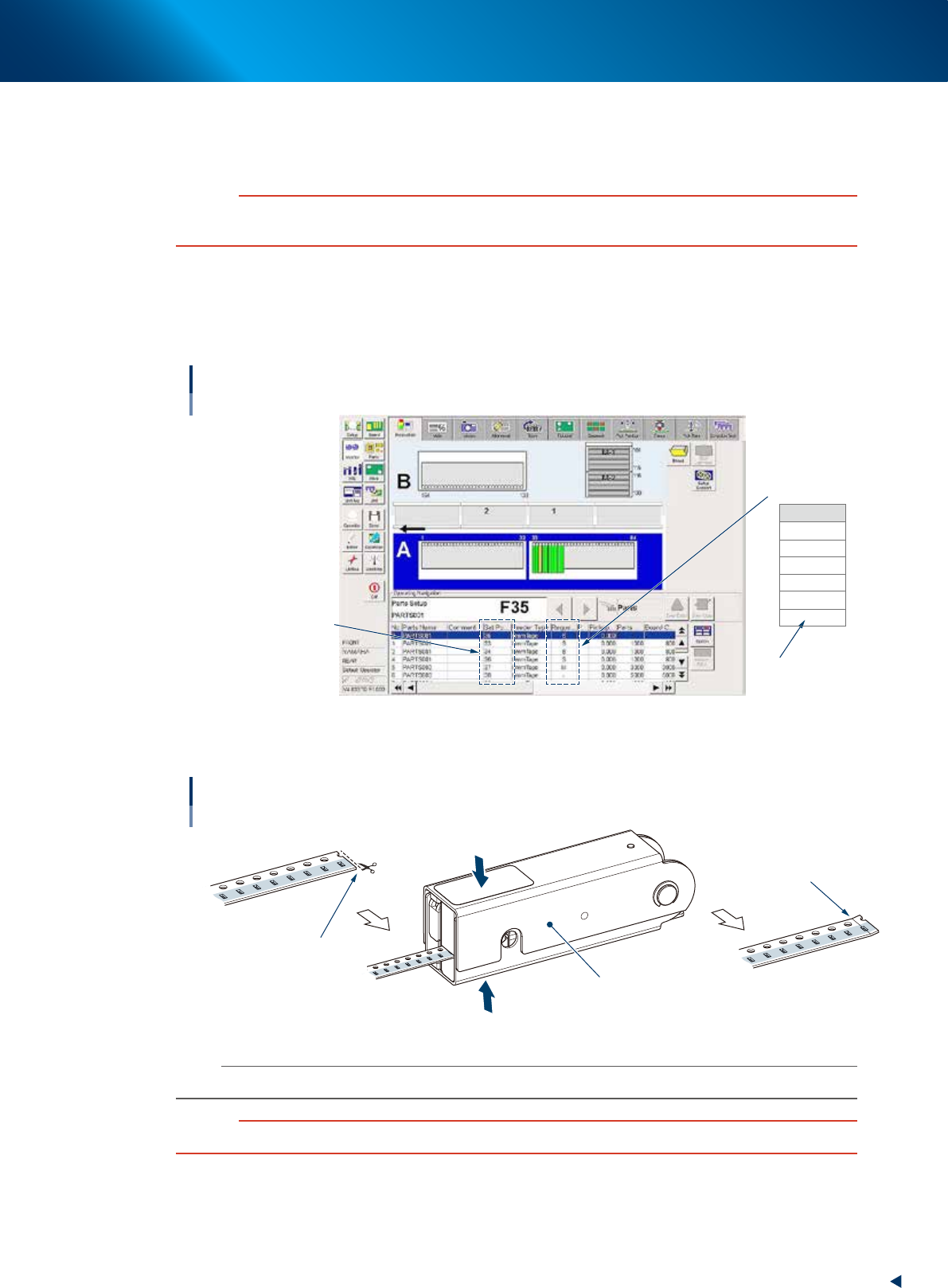
1
Prepare component tape to be set.
1. Open the [Monitor] - [Production] tab.
2. Check the parts name and set position in "Operating Navigation" box, and the tape guide
type in "Request size" of parts list.
Operating Navigation box
Tape guide type
Parts name,
Feeder set position
Auto Loading Feeder
is not used.
Request size
LL
L
M
S
2S
-
64301-KLU-40
2
Cutting/Folding top of component tape.
Cutting/Folding top of component tape
Cut from pocket side.
Check folded position.
Tape leveler
Insert component tape and
grip top and bottom of tape leveler.
63302-KLU-40
n
NOTE
See "1.2 Folding top of component tape" in chapter 2 for more detail.
c
CAUTION
Make sure to cut and fold the top of component tape correctly. Otherwise component tape may not be loaded.