ALFeeder_E.pdf - 第106页
Chapt er 5 Sp ecific ation s Contents 1. Auto loading feeder specifications 5-1 1. 1 Basic specification 5-1 1.2 Feeder type (model)/available component 5-1 1.3 T ape loading/T ape aut o-replace durations 5-2 2. Component…
3. Maintenance / Replacing procedure
4-17
Chapter 4 Maintenance and parts replacement
3.9 Preset holder section
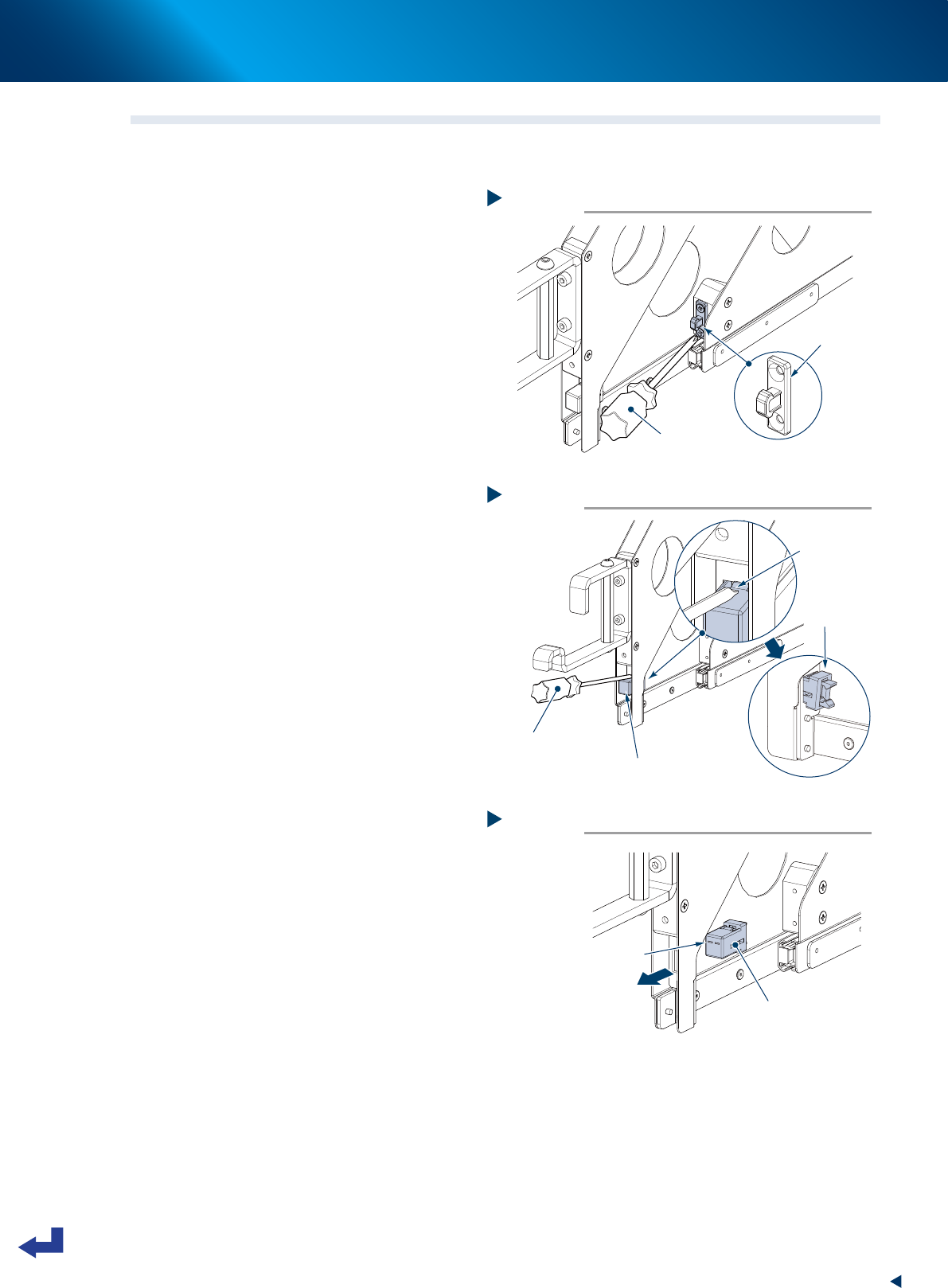
3.9.1 Replacing sliding stopper
1
Replace keeper on sliding side.
Detach keeper on sliding section with Phillips
screwdriver. Then attach new keeper.
2
Detach stopper main unit.
1. Press claw as shown at right with flat-head
screwdriver to move it inside.
2. Press the other side of claw to detach
stopper main unit from preset holder.
3
Attach stopper main unit.
Face up the surface with hole as shown at right.
Then Insert stopper main unit from inside.
4
Check the operation.
Press sliding section of preset holder to check
the operation of locking/unlocking.
Step 1
Replacing keeper
Phillips screwdriver
Keeper
63430-KLU-30
Step 2
Detaching stopper main unit
Flat-head screwdriver
Stopper main unit
Detaching crow.
(2 positions)
Pull out.
63431-KLU-30
Step 3
Attaching stopper main unit
Face up surface with hole.
Stopper main unit
63432-KLU-30

Chapter 5 Specifications
Contents
1. Auto loading feeder specifications 5-1
1.1 Basic specification 5-1
1.2 Feeder type (model)/available component 5-1
1.3 Tape loading/Tape auto-replace durations 5-2
2. Component tape reference specifications 5-3
2.1 Limitation of meandering 5-3
2.2 Tensile testing 5-3
2.3 Top of component tape 5-4
2.4 End of component tape 5-4
2.5 Component position in pocket 5-4
2.6 Tensile strengths of carrier tape/cover tape 5-5
2.7 Size of 8mm tape reel 5-5
1. Auto loading feeder specifications
5-1
Chapter 5 Specifications
1. Auto loading feeder specifications
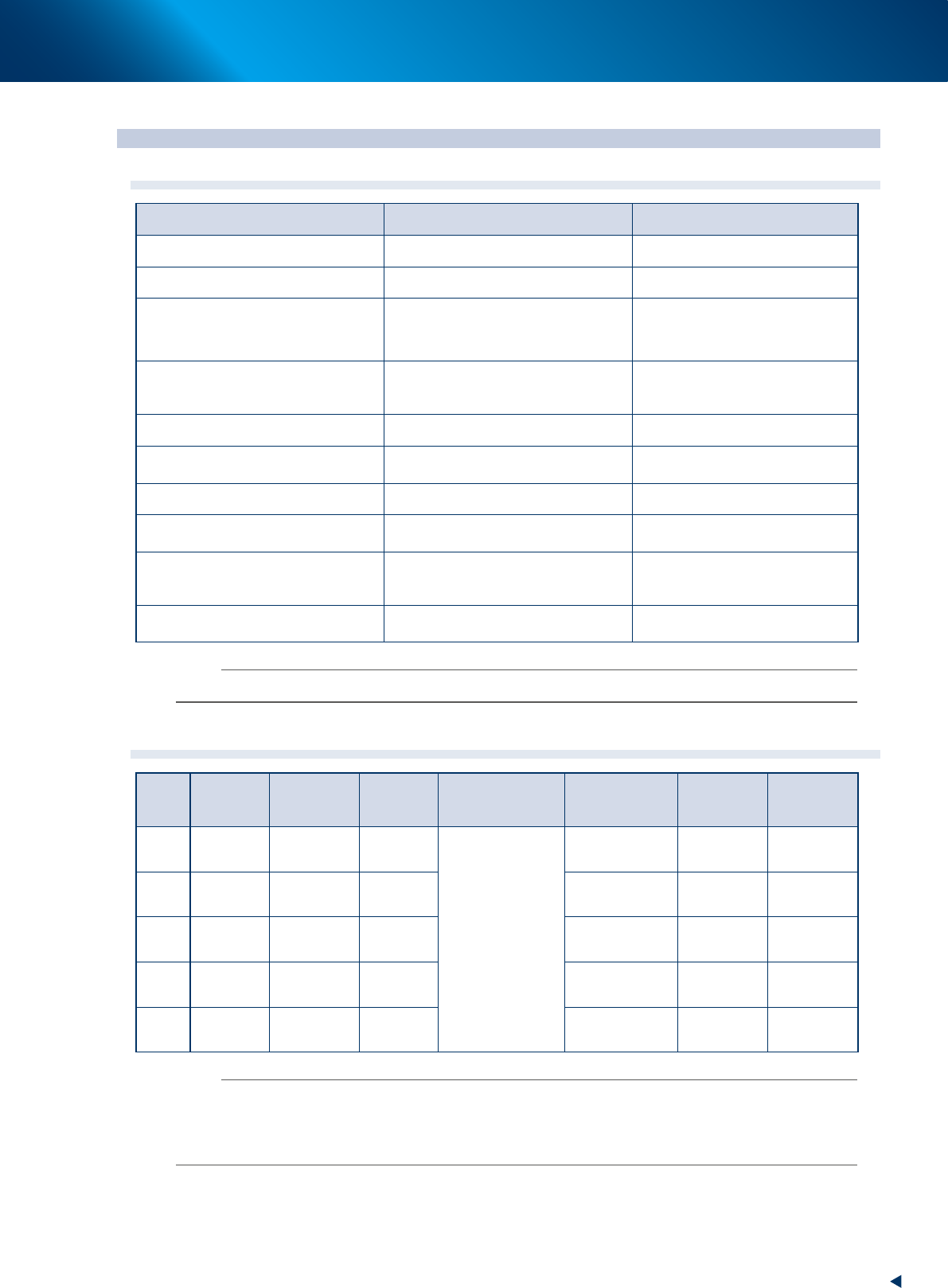
1.1 Basic specification
Item Description Remark
External dimension (mm) L 548 × W 11.5 × H 280
Weight (kg) 1.5
Compatible models
YSM20, YSM20W, YSM20R, YSM40R, YRM20
YSM10, YS24, YS12, YS12P/F YSM40,
YS24X, YS100, YS88 , YRM20 and more
Following are incompatible:
-Without tape cutter
-YS100FNC head model
Available carrier tape
Material: Paper
Width: 8 mm
Maximum thickness: 1 mm
Limitation applies.
Feed pitch 2 mm / 4mm
Available reel specification
Width: 14.4 mm or less
Diameter: 382 mm or less
13.0 mm or less when using preset
holder
8 mm converted loading witdh 12 mm pitch: 1
Shortest length of component tape to
load
400 mm or longer
Longest length of tape without
component from end available for auto
supply of spare components
300 mm or shorter
600 mm or shorter when using
IT-Option
Feeder type (available component)
2S (0603/1005), S(1005), M(1608),
L(2012), LL(3216))
Size labels on tape guide and
operation panel must be same.
n
NOTE
See the product specification for detail about compatible models.
1.2 Feeder type (model)/available component
Model Tape width Feed pitch
Tape
material
Standard
Reel Dia.× Width
External
dimension (mm)
Cover tape
Seal witdh
(mm)
Available
component
size
2S 8 mm 2 mm Paper
∅
180×14.4 mm
0.4 < X
≤
1.0
0.2 < Y
≤
0.5
1.4 or more 0603/1005
S 8 mm 2 mm Paper
0.6 < X
≤
1.0
0.3 < Y
≤
0.85
1.4 or more 1005
M 8 mm 2 mm / 4 mm Paper
1.0 < X
≤
1.6
0.3 < Y
≤
1.6
2.1or more 1680
L 8 mm 2 mm / 4 mm Paper
1.6 < X
≤
2.0
0.3 < Y
≤
2.0
2.6 or more 2012
LL 8 mm 2 mm / 4 mm Paper
2.0 < X
≤
3.2
0.3 < Y
≤
2.5
3.8 or more 3216
n
NOTE
• Splicing tape is unavailable.
• Using splicing tape may result in pickup error.
• Splicing position cannot be detected.
• The 0603 (0201) size of 2S feeder supports only magnetic components.