ALFeeder_E.pdf - 第30页
Chapt er 2 Handli ng c omponent t ape Contents 1. Preparation for loading component tape 2-1 1. 1 Cutting component tape 2-1 1. 1. 1 New component tape 2-1 1. 1. 2 Component tape t o be r eloaded 2-2 1. 1. 3 Precautions …
1. Overview
1-17
Chapter 1 Overview
█
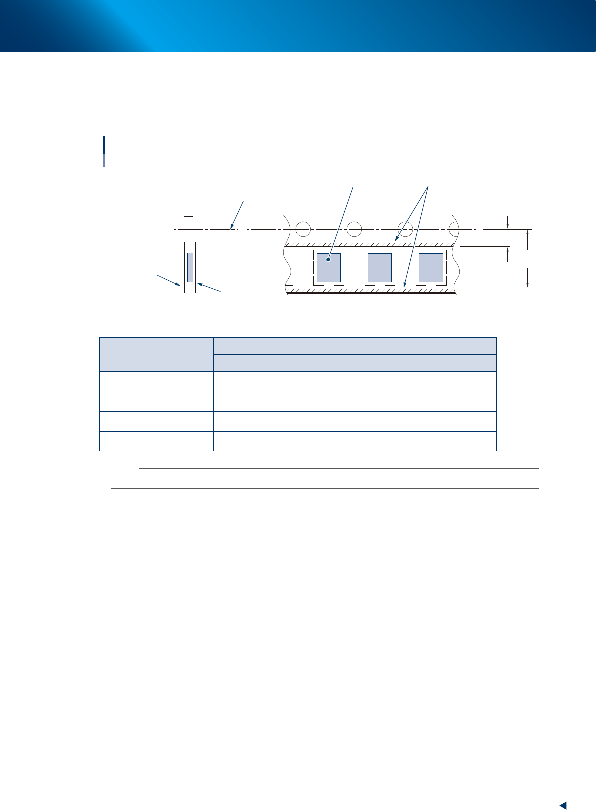
JEITA standard (Paper tape specifications for Auto loading feeder)
It is recommended to use a tape package complying with JEITA ET-7105 for the effective use of Auto
loading feeder. The following is an excerpt from JEITA requirements and sizes of paper tape packages
available for Auto loading feeder.
Tape sizes complying with JEITA
Paper tape package for Auto loading feeder
Bottom cover tape
M
1
M
2
Top cover tape
Adhesive
Component
Feed hole center
63120-KLU-20
►
Required sizes of adhesive for cover tape
Nominal component size
Required size (calculated value)
M
1
M
2
1005M 2.6 or less 4.4 or more
1608M 2.4 or less* 4.6 or more*
2012M 2.2 or less* 4.8 or more*
3216M 1.7 or less 5.3 or more
n
NOTE
It is desirable that adhesive is approx. 0.2 mm away from component pocket.
►
Required specification of cover tape adhesive
The cover tape adhesive for Auto loading feeder is the heat sealing type only.
►
Required specification of trailer maximum length
It is desirable that trailer maximum length for Auto loading feeder is 300 mm or less.

Chapter 2 Handling component tape
Contents
1. Preparation for loading component tape 2-1
1.1 Cutting component tape 2-1
1.1.1 New component tape 2-1
1.1.2 Component tape to be reloaded 2-2
1.1.3 Precautions about cutting position of component tape 2-3
1.1.4 Cutting component tape 2-4
1.2 Folding top of component tape 2-6
1.2.1 Folding top of component tape 2-6
2. Loading/Unloading component tape 2-7
2.1 Loading component tape 2-7
2.1.1 Standard type 2-7
2.1.2 With IT Option 2-10
2.2 Unloading component tape 2-13
1. Preparation for loading component tape
2-1
Chapter 2 Handling component tape
1. Preparation for loading component tape
1.1 Cutting component tape
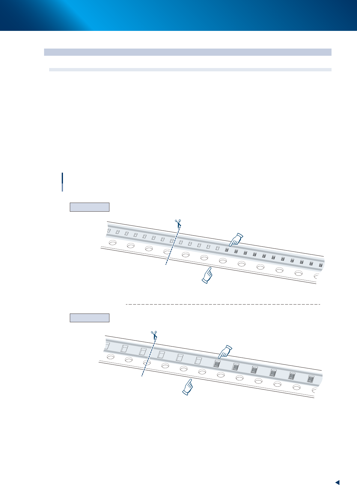
Cut the top of component tape as below depending on the types of tape and the tape condition of use.
1.1.1 New component tape
►
2 mm feed pitch
Cut the side of 4th feed hole from a feed hole on the same line as pocket with first component.
If the feed hole is not on the same line as pocket with first component, cut the side of 4th feed hole from
feed hole on the line between last empty pocket and first pocket with component.
►
4 mm feed pitch
Cut the center of 4th feed hole from feed hole on the line between last empty pocket and first pocket
with component.
2
1
3
4
1
2
3
4
2 mm feed pitch
4 mm feed pitch
Cutting positions of component tape
New component tape (8 mm width)
Stop position when loading is completed
Stop position when loading is completed
First pickup position
Cutting position: Side of feed hole
Cutting position: Center of feed hole
First pickup position
63201-KLU-30