ALFeeder_E.pdf - 第94页
3. Maintenance / Replacing procedure 4-6 Chapter 4 Maintenance and parts replacement 3 Clean tape guide. Clean groove of tape guide an d tape path with air blow tool or the similar . n NOTE When g roove of tape gu ide an…
3. Maintenance / Replacing procedure
4-5
Chapter 4 Maintenance and parts replacement
3. Maintenance / Replacing procedure
3.1 Tape guide
c
CAUTION
Do not disassemble tape guide. The original accuracy is not ensured by reassembling tape guide.
3.1.1 Cleaning
1
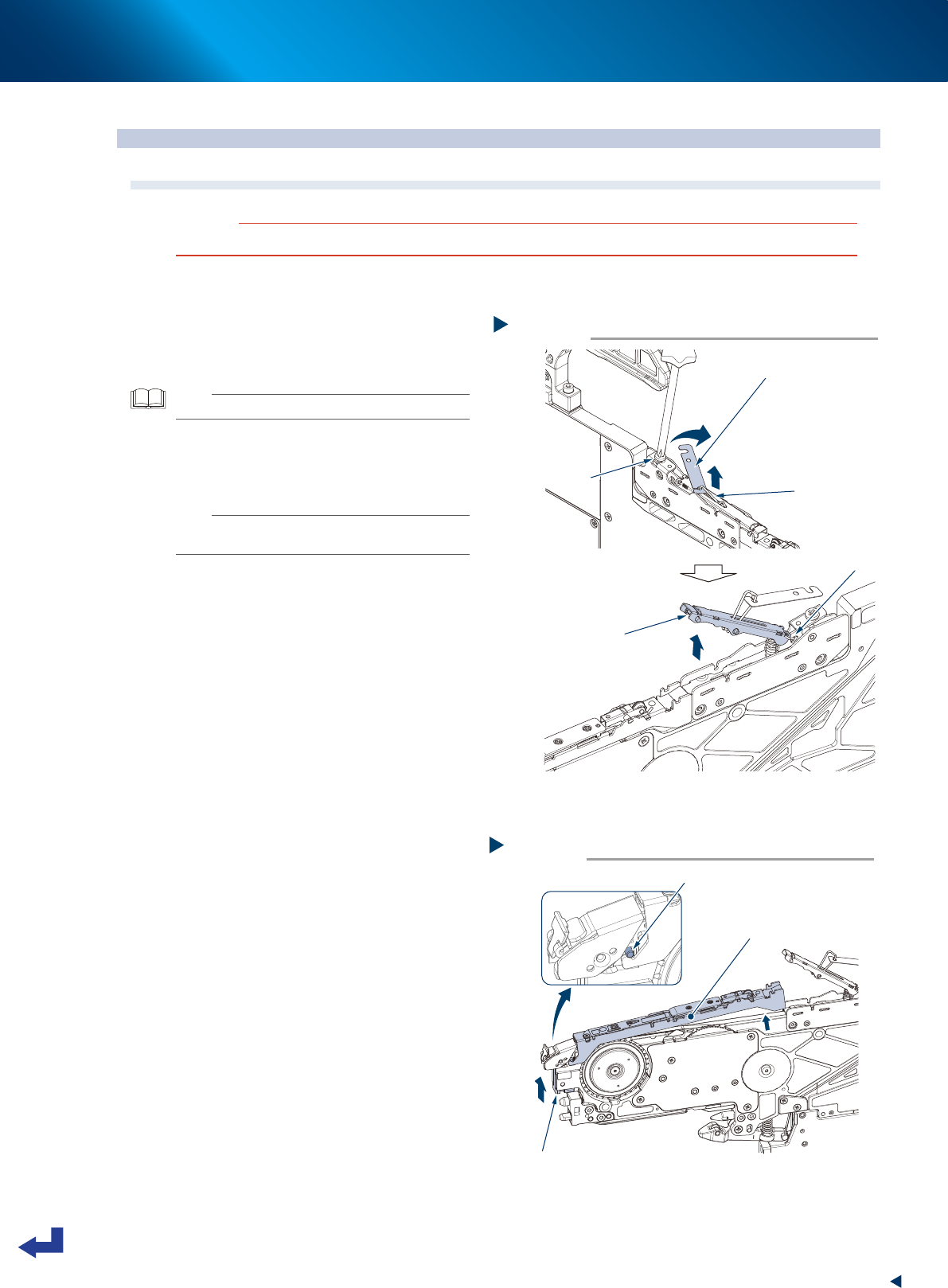
Detach tape guide rear lever.
1. Loosen a screw mounting lever plate with
Phillips screwdriver.
TIP
It is not necessary to remove a mounting screw.
2. Move lever plate to arrow's direction in the
figure on the right.
3. Raise up lever pin to pull up tape guide rear
lever.
n
NOTE
As tape guide rear lever is connected to Auto loading
feeder body with clip, it cannot be detached.
2
Unlock front lever.
1. Push up front lever to loosen a pin locking
tape guide.
2. Detach tape guide from Auto loading feeder
body.
Step 1
Detaching tape guide rear lever
Lever pin
Lever plate
Mounting screw
Tape guide rear lever
Lift up.
Clip
63402-KLU-30
Unlocking front lever
Step 2
Front lever
Tape guide
Pin
63403-KLU-40
3. Maintenance / Replacing procedure
4-6
Chapter 4 Maintenance and parts replacement
3
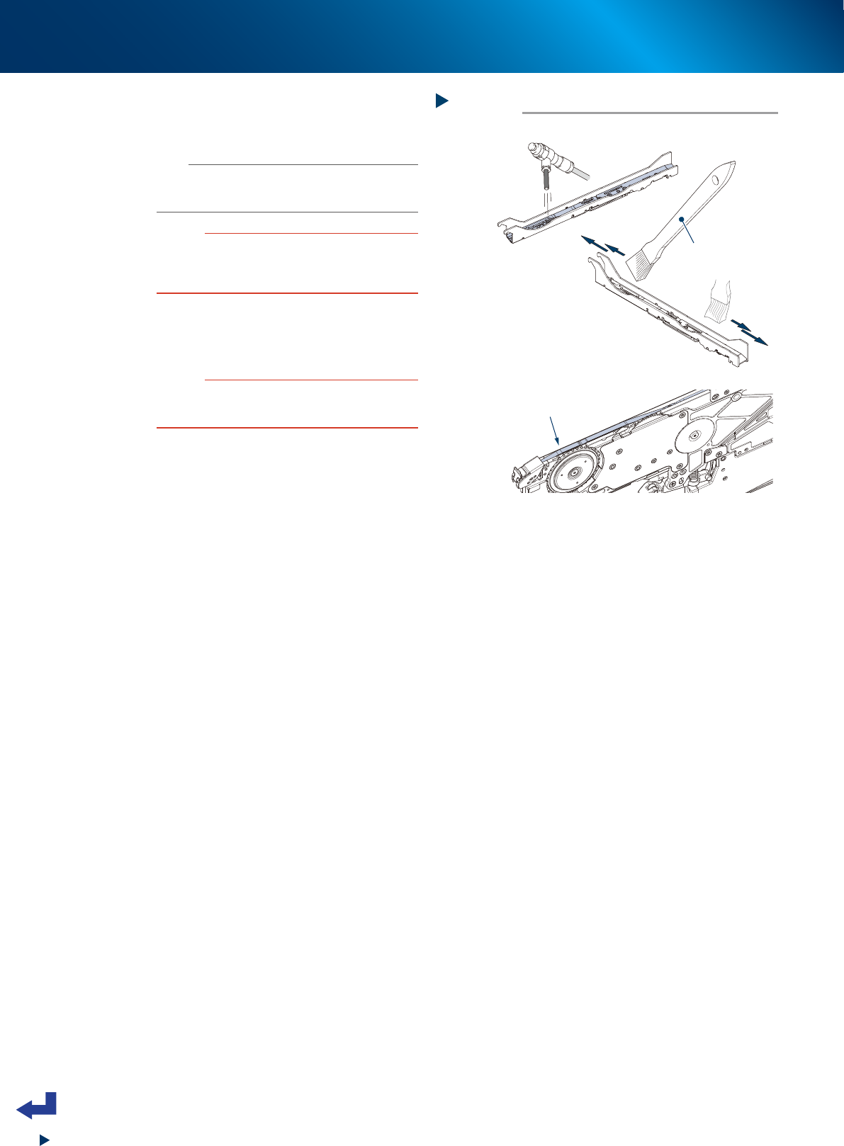
Clean tape guide.
Clean groove of tape guide and tape path with
air blow tool or the similar.
n
NOTE
When groove of tape guide and tape path cannot be
clean with air blow, clean them with tape guide brush
(option).
c
CAUTION
Do not use solvent or alcohol for cleaning tape guide.
Doing so may result in functional failure.
Touching leaf spring in tape path with bare hand may
discolors the leaf spring.
4
Return tape guide to original position.
Attach tape guide in reverse order of
detaching.
c
CAUTION
Take care when cleaning multiple tape guides.
When attaching them, check the tape guide type (2S/S/
M/L/LL) and return to the same size feeder.
Step 3
Cleaning tape guide and tape path
Air blow tool or the similar
Leaf spring
Tape guide brush
(option)
Tape path
63404-KLU-30
3. Maintenance / Replacing procedure
4-7
Chapter 4 Maintenance and parts replacement
3.1.2 Replacing tape guide assembly
The replacement of tape guide assembly is required upon deforming the body of tape guide or damaging the
blade section.
c
CAUTION
Do not disassemble tape guide. The original accuracy is not ensured by reassemblying tape guide.
c
CAUTION
5 sizes of tape guides are provided, according to the available component syze.
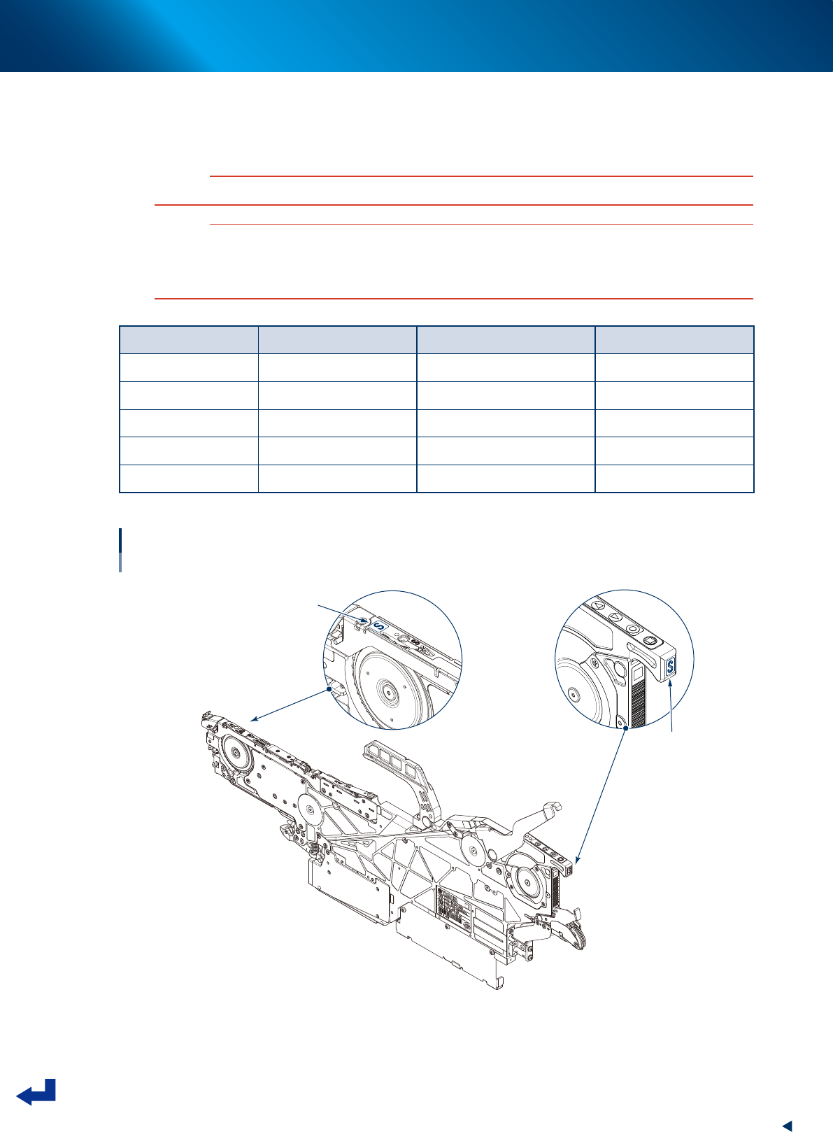
Make sure to check the type engraved on tape guide and displayed on operation panel to avoid mis attachment. If
attaching incorrect type tape guide assembly, Auto loading feeder will not operate correctly. See "1.1 Part names and
functions" in chapter 1.
Available component size: Unit is mm. Figures in ( ) are sizes in inches.
Size display/Engraving Available component size Name Part number
2S 0603 (0201)* / 1005 (0402) Tape guide assembly (2S) KLU-MC1M1-40X
S 1005 (0402) Tape guide assembly (S) KLU-MC1M1-00X
M 1608 (0603) Tape guide assembly (M) KLU-MC1M1-10X
L 2012 (0805) Tape guide assembly (L) KLU-MC1M1-20X
LL 3216 (1206) Tape guide assembly (LL) KLU-MC1M1-30X
*0603(0201) size supports only magnetic components.
Checking feeder type
Type display
Operation panel
Type display
Tape guide
Type display
63100-KLU-40