ALFeeder_E.pdf - 第14页
1. Overview 1-2 Chapter 1 Overview 1. Loading unit Used upon setting newly or presetting the component tape. Pull out by sliding to refill the component tape and insert it to feeder body after setting the tape, illustrat…
1. Overview
1-1
Chapter 1 Overview
1. Overview
Auto Loading Feeder supplies component tape to a mounter. This manual describes the functions,
handling, and operations of Auto Loading Feeder for those who have finished the basic training of
mounter.
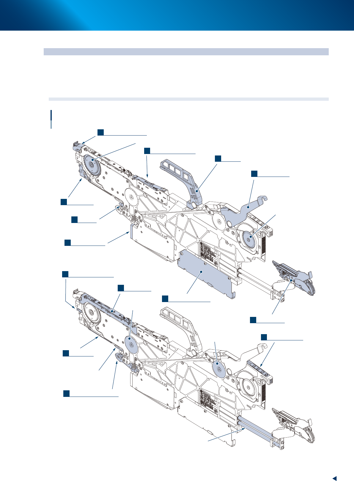
1.1 Part names and functions
Part names
Loading unit
Loading side
sprocket
Feeding side sprocket
unclamp lever
Board connector
Tail pin
Reel holder bracket
Handle
Front block
Tape guide rear lever
Discharge assembly
Clamp lever assembly
Under rail
Tape guide front lever
Loading motor
Feeding motor
Operation panel
Tape guide
Loading unit shaft
Under plate
3
1
2
14
6
4
5
8
7
9
10
11
12
13
63101-KLU-50
1. Overview
1-2
Chapter 1 Overview
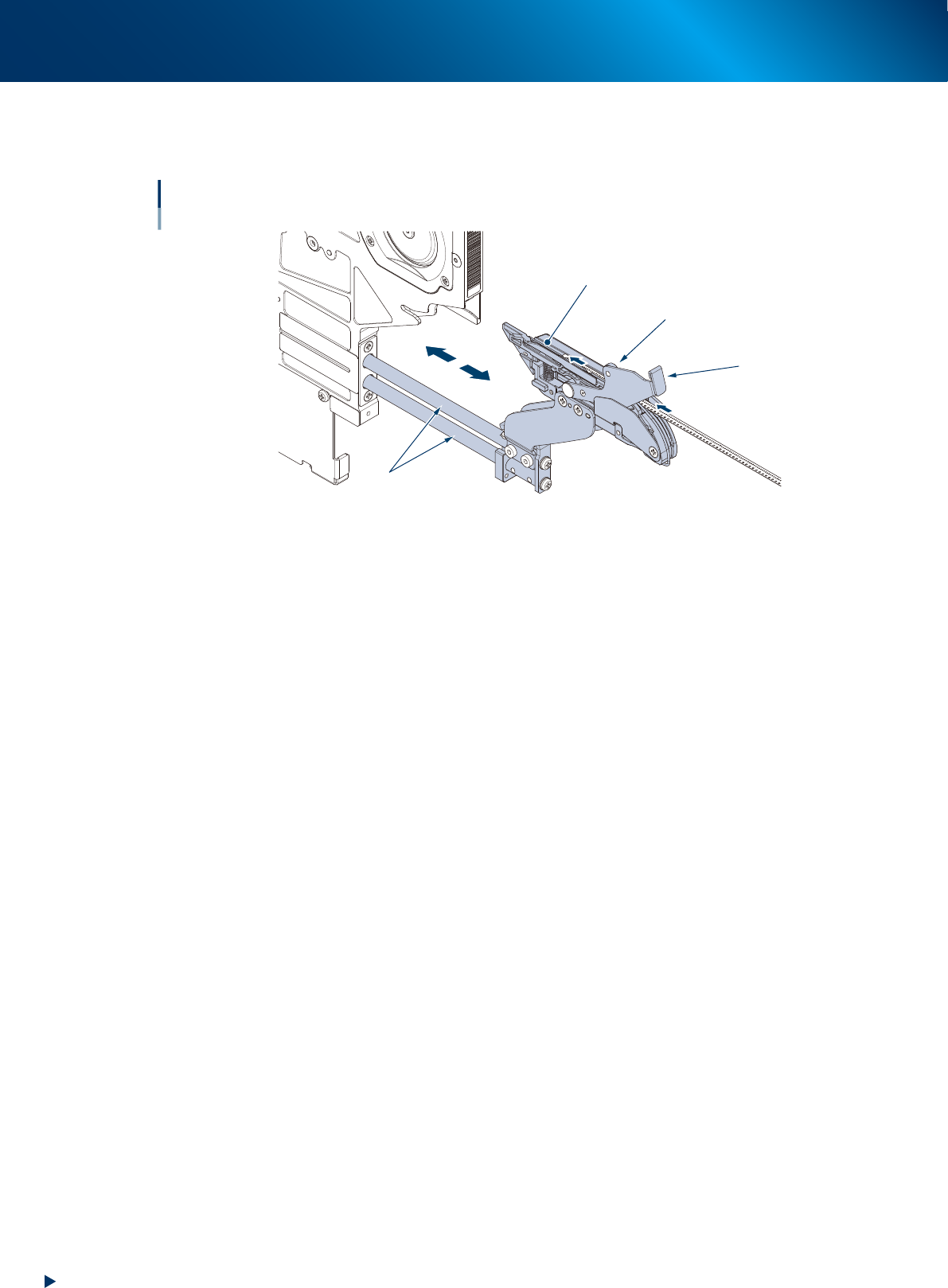
1. Loading unit
Used upon setting newly or presetting the component tape. Pull out by sliding to refill the component
tape and insert it to feeder body after setting the tape, illustrated below.
Loading unit
Slide shaft
Position of tape setting
Tape clamp lever
Tape clamp roller
63102-KLU-50
2. Unclamp lever
Used upon attaching/detaching the feeder by opening/closing the clamp lever assembly. It unclamps
upon gripping, clamps upon releasing.
3. Handle
Used to bring the auto loading feeder. The upper part of this handle plays the role of guide upon
inserting into the feeder exchange carriage.
4. Tape guide rear lever
Used to fix the rear side of tape guide. This lever should be detached upon replacing the tape guide.
5. Ejection tip
Used to cover the component tape ejection slot. The rubber part installed on tip fills the gap to prevent
that the ejected component tape returns from the slope side.
6. Front block
Used to be inserted to the auto loading feeder upon attaching to fix the equipment for positioning.
7. Tail pin
Used to position the auto loading feeder by inserting to the equipment side to fix it, as same as the front
block.
8. Board connector
Used as the power and signal connector for the auto loading feeder.
9. Reel holder bracket
Used to support the rear side of auto loading feeder from sinking. Also, used to hung the tape reels on
the left and right hook upon bringing around.
1. Overview
1-3
Chapter 1 Overview
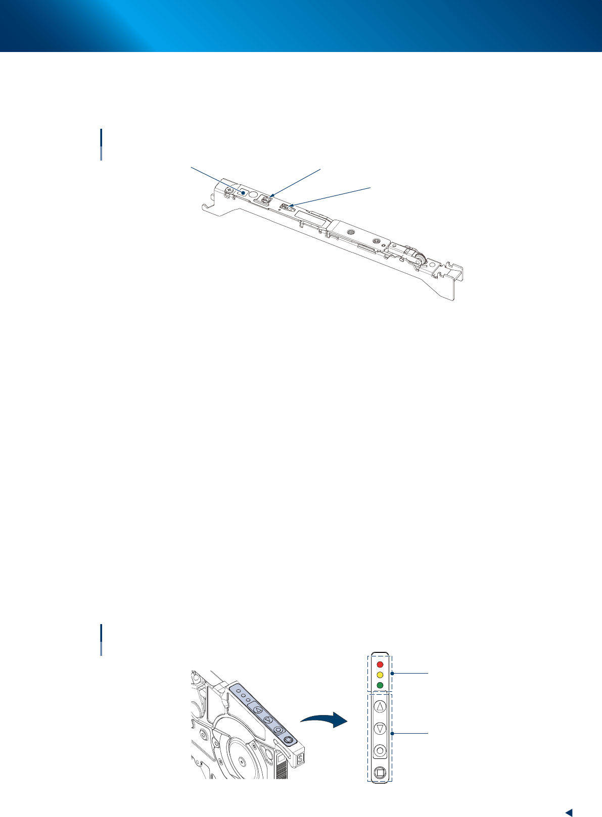
10. Tape guide
The tape guide contains a blade within, and cut the cover of component tape to open, then close the
tape after picking up the component. The dedicated tape guides are provided for each component
sizes.
Type display
(S, M, L, LL)
Tape guide
Pick up position
Blade
63103-KLU-40
11. Tape guide front lever
Used to fix the front side of tape guide. Push up the lever to detach tape guide.
12. Under rail
Used to prevent the floating up by sliding along feeder bank and getting stuck to it, upon attaching the
auto loading feeder.
13. Clamp lever assembly
Used to clamp/unclamp the feeder by opening/closing. It unclamps upon gripping the unclamp lever,
clamps upon releasing.
14. Operation panel
LEDs
The feeder status is indicated by flashing and lighting up with 3 LED colors (Red, Yellow, and Green).
The main indications are "Setup change" and "Out of components".
Operation buttons
The [FEED] button feeds component tape.
The continuous feed is available by pressing and holding the [FEED] button.
The [FUNC] button is used with the [FEED] button or [BACK] button.
[FUNC]+[FEED]: Ejects component tape forcibly from the front side of feeder.
[FUNC]+[BACK]: Unloads component tape to the rear of feeder.
LED1
LED2
LED3
FEED
BACK
FUNC
LOAD
Buttons on operation panel and LEDs
LEDs
Operation buttons
63104-KLU-30