ALFeeder_E.pdf - 第67页
2. Preaparation for operation 3-21 Chapter 3 Setting up 3. Close the clamp unit and move the loading unit just before the end to make it not open. 4. While pressing the tape clamp lever , insert the component tape to the…
2. Preaparation for operation
3-20
Chapter 3 Setting up
3
S
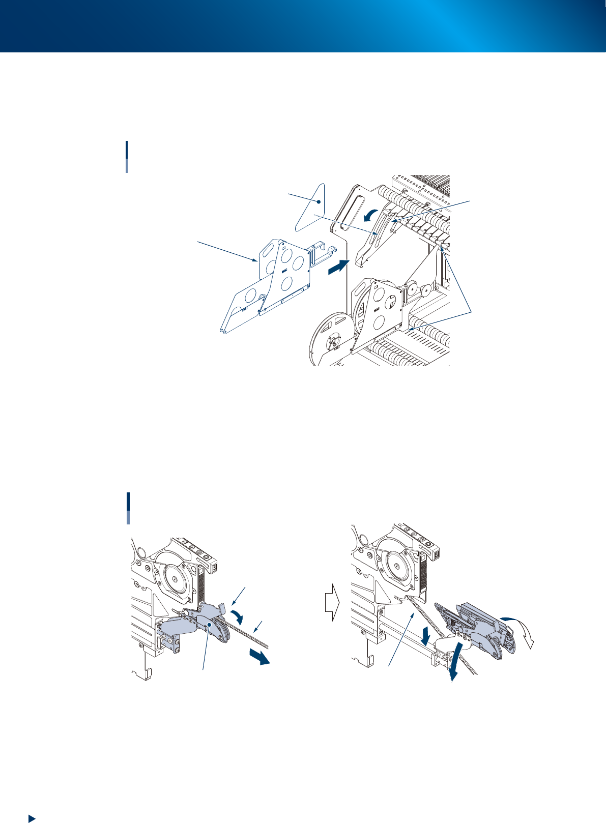
et the preset holder when the component tape is newly set
.
1. Move down the reel holder of the feeder No. to be set Auto loading feeder.
2. Insert the preset holder and hang the hooks on the boss on the rear of reel holder.
3. Attach a reel holder pad to the reel holder.
Setting preset holder
Example: Feeder exchange carriage for YSM20 series
Reel holder pad
Reel holder
Position to attach partition
Preset holder
63325-KLU-50
4
Set the tape reel, to be added newly or to be supplied, to preset holder.
5
Set the component tape to the loading unit.
1. While pressing down the tape clamp lever and pull the loading unit to front end.
2. (If the 1st reel spplies components) the clamp unit opens left and right by releasing the tape
clamp lever, the component tape in operation is fallen down below the loading unit.
Pulling out loading unit
Moving down the component tape in operation
Clamp unit opens
by releasing tape clamp lever
Tape clamp lever
Loading unit
Tape component
in operation
Tape component
in operation
63331-KLU-00
2. Preaparation for operation
3-21
Chapter 3 Setting up
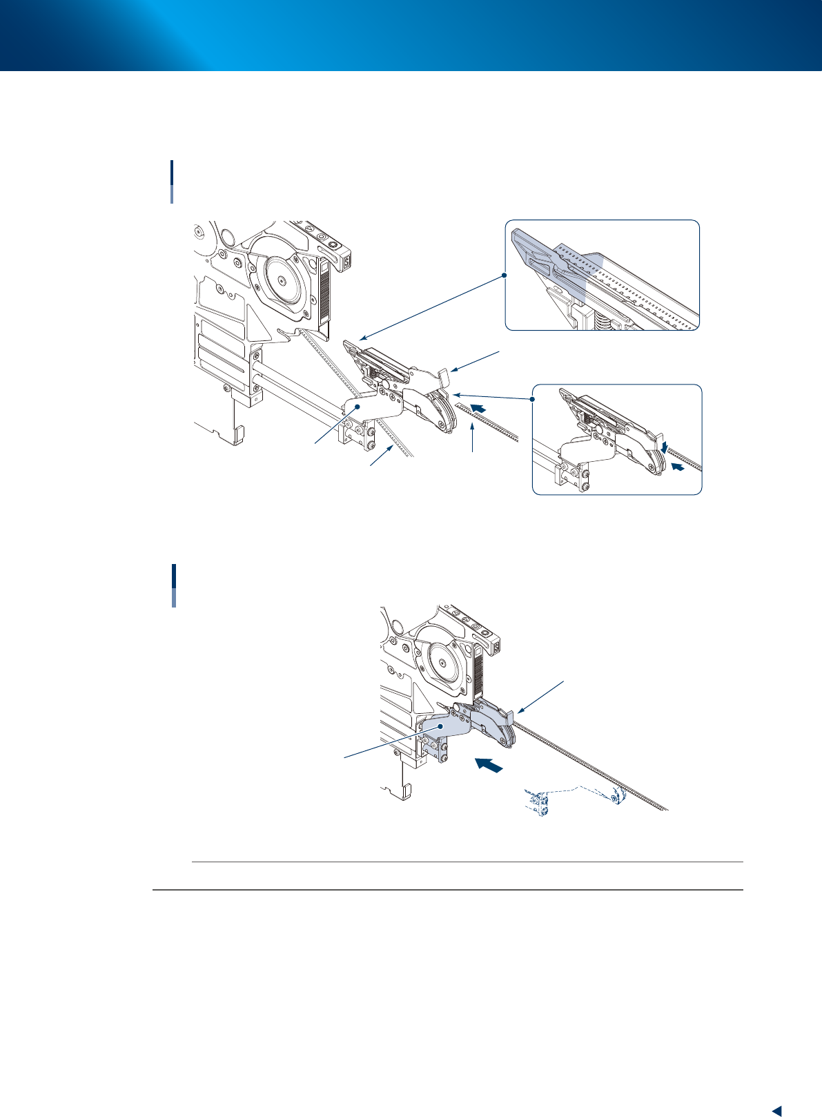
3. Close the clamp unit and move the loading unit just before the end to make it not open.
4. While pressing the tape clamp lever, insert the component tape to the loading unit, then insert
the top of component tape to the set area as shown in the figure below.
Setting component tape
Loading unit
Component tape
to be added
Component tape in operation
Tape clamp lever
Keep pressing down
tape clamp lever
Tape set area
Clamp unit
Set top of component
tape in this area
63305-KLU-50
5. Insert the loading unit into feeder body and release the tape clamp lever.
Inserting loading unit
Loading unit
Tape clamp lever
63332-KLU-00
n
NOTE
A loading error may occur unless the loading unit is inserted into the end.
2. Preaparation for operation
3-22
Chapter 3 Setting up
5
Check the component tape setting.
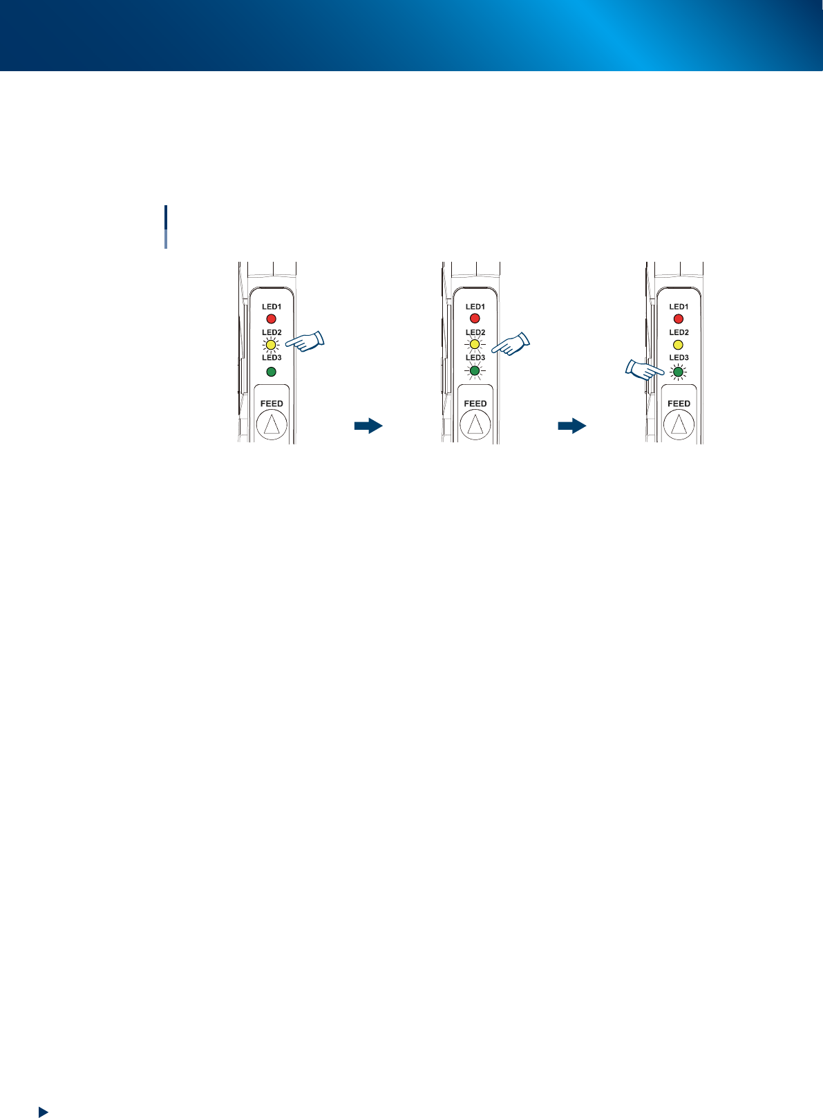
The component tape is set correctly if the followings are applied.
1. The yellow LED lights up for 1 second if the component tape insertion is detected.
2. The yellow and green LEDs flash simultaneously for 4 seconds.
3. The green LED lights up after completing the component tape setting.
Yellow and green LEDs flash
simultaneously for 4 sec.
Yellow LED lights up for 1 sec.
Green LED lights up.
Completing
Completing component tape setting
Without IT Option
63306-KLU-30
6
Start the operation.
When the reel was newly set.
Pressing [START] button loads component tape, set in the loading unit, to pickup position and starts
operation.
When the reel was preset.
If the component tape in operation becomes empty, other component tape set in the loading unit
loads to pickup position and supplying component is continued.