ALFeeder_E.pdf - 第108页
1. Auto loading feeder specifications 5-2 Chapter 5 Specifications 1.3 T ape loading/T ape auto-r eplace durations No Item Duration Description 1 T ape loading duration Approx. 5 sec. Duration from starting component tape …
1. Auto loading feeder specifications
5-1
Chapter 5 Specifications
1. Auto loading feeder specifications
1.1 Basic specification
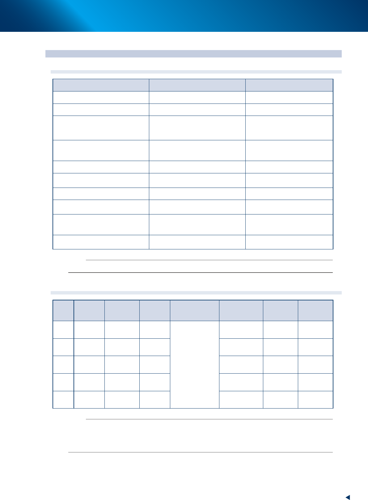
Item Description Remark
External dimension (mm) L 548 × W 11.5 × H 280
Weight (kg) 1.5
Compatible models
YSM20, YSM20W, YSM20R, YSM40R, YRM20
YSM10, YS24, YS12, YS12P/F YSM40,
YS24X, YS100, YS88 , YRM20 and more
Following are incompatible:
-Without tape cutter
-YS100FNC head model
Available carrier tape
Material: Paper
Width: 8 mm
Maximum thickness: 1 mm
Limitation applies.
Feed pitch 2 mm / 4mm
Available reel specification
Width: 14.4 mm or less
Diameter: 382 mm or less
13.0 mm or less when using preset
holder
8 mm converted loading witdh 12 mm pitch: 1
Shortest length of component tape to
load
400 mm or longer
Longest length of tape without
component from end available for auto
supply of spare components
300 mm or shorter
600 mm or shorter when using
IT-Option
Feeder type (available component)
2S (0603/1005), S(1005), M(1608),
L(2012), LL(3216))
Size labels on tape guide and
operation panel must be same.
n
NOTE
See the product specification for detail about compatible models.
1.2 Feeder type (model)/available component
Model Tape width Feed pitch
Tape
material
Standard
Reel Dia.× Width
External
dimension (mm)
Cover tape
Seal witdh
(mm)
Available
component
size
2S 8 mm 2 mm Paper
∅
180×14.4 mm
0.4 < X
≤
1.0
0.2 < Y
≤
0.5
1.4 or more 0603/1005
S 8 mm 2 mm Paper
0.6 < X
≤
1.0
0.3 < Y
≤
0.85
1.4 or more 1005
M 8 mm 2 mm / 4 mm Paper
1.0 < X
≤
1.6
0.3 < Y
≤
1.6
2.1or more 1680
L 8 mm 2 mm / 4 mm Paper
1.6 < X
≤
2.0
0.3 < Y
≤
2.0
2.6 or more 2012
LL 8 mm 2 mm / 4 mm Paper
2.0 < X
≤
3.2
0.3 < Y
≤
2.5
3.8 or more 3216
n
NOTE
• Splicing tape is unavailable.
• Using splicing tape may result in pickup error.
• Splicing position cannot be detected.
• The 0603 (0201) size of 2S feeder supports only magnetic components.

1. Auto loading feeder specifications
5-2
Chapter 5 Specifications
1.3 Tape loading/Tape auto-replace durations
No Item Duration Description
1 Tape loading duration Approx. 5 sec.
Duration from starting component tape loading after setting top of
component tape to specified position on feeder to completing component
tape feeding to pickup position.
2 Tape auto-replace duration Approx. 8 sec.
Duration to replace component tape in operation (1st tape) that runs out
of component with component tape to be added (2nd tape) automatically.
n
NOTE
• Durations above vary depending on the component tape size or feed pitch.
• Tape auto-replace duration includes discharging time of 1st tape that runs out of component.
2. Component tape reference specifications
5-3
Chapter 5 Specifications
2. Component tape reference specifications
2.1 Limitation of meandering
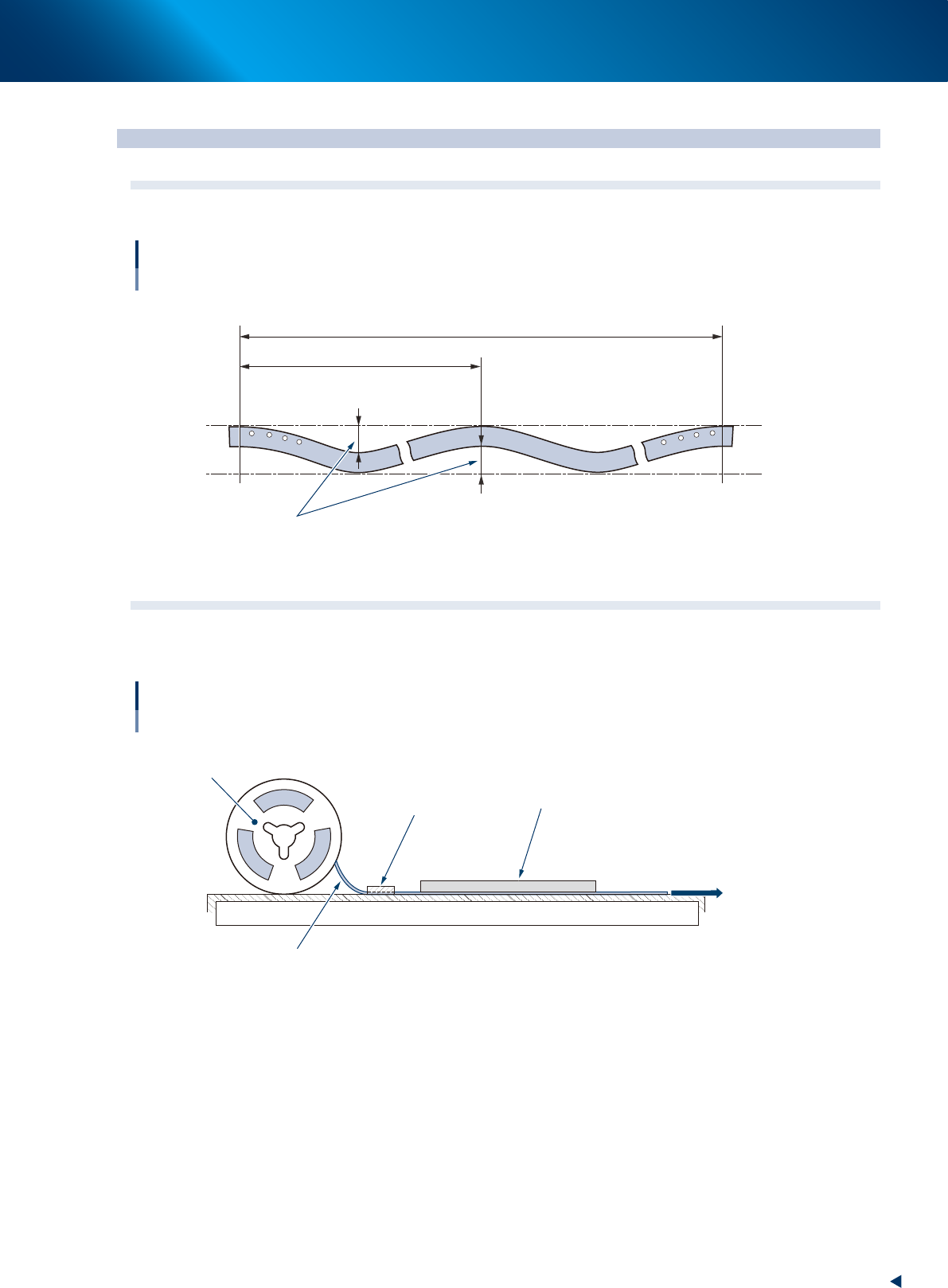
The meandering must be 1 mm or less per 100 mm within the span of 250 mm.
Limitation of component tape meandering
100
1 or less
250
Unit: mm
63505-KLU-30
2.2 Tensile testing
Fix one side of component tape. Pull the component tape applying a force of 1 N (102 gf). Place a
transparent plastic board with scale that is also a weight to measure the component tape.
Tensile testing
Reel
Apply a force
of 1N.
1N: 102 gf
Component tape
Fixing point
Transparent plastic board with scale
that is also a weight
63506-KLU-30