MR8740T_Quick guide_eng_20191016H.pdf - 第148页
142 Specications of the Options Specications of output connector Connector used: 25 pins, female, locking-block screws #4-40 Connector pin-out Pin Signal name Pin Signal name 1 NC 14 CH8_GND 2 CH8_RESERVE 15 CH8_OUTPUT…
141
Specications of the Options
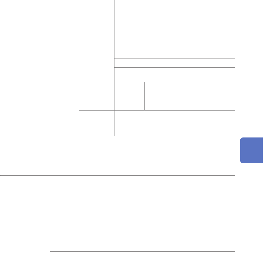
Self-diagnosis
Operation
comprehensive
test
The instrument outputs the following signals with the
voltage and current functions, measuring them using the
internal measurement circuit.
If a measured value differs from the corresponding output
setting value by more than the threshold value, the
instrument gives itself a fail judgment.
The instrument returns a judgment result, output setting
value, and measured value in response to a query.
The threshold value of 0% causes the instrument to fail to
judge.
Voltage function 0 V, .0.5 V, 5 V
Current function 0 µA, 50 µA, 55 µA, 250 µA,
275 µA, 1 mA, 1.1 mA, 5 mA
Threshold
value
Setting
range
0% to 10%
Setting resolution: 1%
Default
setting
0%
Simple test Using the internal measurement circuit, the instrument
measures an signal outputted when a command is sent.
The instrument returns an output setting value and
measured value in response to a query.
Switching OUTPUT
terminals
Relay switching time
Operation
OPEN:
SHORT:
NORMAL:
Opens the circuit of the OUTPUT terminal.
Connects the OUTPUT terminal to ground. (10
Ω
or less with a
load current of 5 mA)
Outputs the specied signal across the OUTPUT terminal.
Default
setting
OPEN
Connected-object
presumption
Operation With the resistance generation function, the instrument presumes an output
resistance value of the connected object, capacitance value between the
OUTPUT and GND terminals, and voltage value across them.
Optimizes a resistance-generation response coefcient based on the
presumption.
When the time constant based on an output resistance value and inter-
terminal capacitance value is less than 10 ms, the inter-capacitance is
determined to be 0 pF.
Calculation
time
1.6 seconds (max.)
Offset cancel
Operation
Measures an output-circuit offset with the measurement circuit and outputs
a signal with the offset subtracted.
Default
setting
Off
5
Specications
142
Specications of the Options
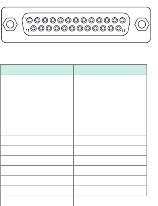
Specications of output connector
Connector used: 25 pins, female, locking-block screws #4-40
Connector pin-out
Pin Signal name Pin Signal name
1 NC 14 CH8_GND
2 CH8_RESERVE 15 CH8_OUTPUT
3 CH7_GND 16 CH7_RESERVE
4 CH7_OUTPUT 17 CH6_GND
5 CH6_RESERVE 18 CH6_OUTPUT
6 CH5_GND 19 CH5_RESERVE
7 CH5_OUTPUT 20 CH4_GND
8 CH4_RESERVE 21 CH4_OUTPUT
9 CH3_GND 22 CH3_RESERVE
10 CH3_OUTPUT 23 CH2_GND
11 CH2_RESERVE 24 CH2_OUTPUT
12 CH1_GND 25 CH1_RESERVE
13 CH1_OUTPUT
143
6
Maintenance and Service
WARNING
Touching any of the high-voltage points inside the instrument is very dangerous.
Do not attempt to modify, disassemble, or repair the instrument. Doing so may
cause a re, electric shock, or injury.
Calibration
The calibration period varies depending on the state of the instrument and installation environment.
We recommend that the calibration period be determined in accordance with the state of the
instrument and installation environment. Please contact your authorized Hioki distributor or reseller
to have your instrument periodically calibrated.
Backing up the data
The instrument may be initialized (returned to the factory default settings) when it is repaired or
calibrated.
Before you ask for repair or calibration, it is recommended to back up (save or record) the
measurement conditions and measured data.
Precautions during shipment
Be sure to observe the following precautions:
• To avoid damage to the instrument, remove any accessories and optional equipment from the
instrument. Use the original packing materials the instrument was shipped in. Damage that
occurs during transportation is not covered by the warranty.
• When sending the instrument for repair, be sure to include a memo that describes the problem in
detail.
6 Maintenance and Service
6
Maintenance and Service