MR8740T_Quick guide_eng_20191016H.pdf - 第16页
10 Operation Precautions Handling the instrument and modules DANGER • Do not use the modules or the cables to measure circuits that exceed those ratings or specications. Damage to the instrument or overheating can cause…
9
Operation Precautions
CAUTION
Failure to observe the following precaution may result in bodily injury.
• The instrument weighs about 14 kg (20.8 kg with modules installed in all slots). It
should be moved by at least two people.
• The instrument is heavy. When transporting it, follow your company’s workplace safety
standards to assure safety (for example, by wearing non-slip gloves and protective
footwear).
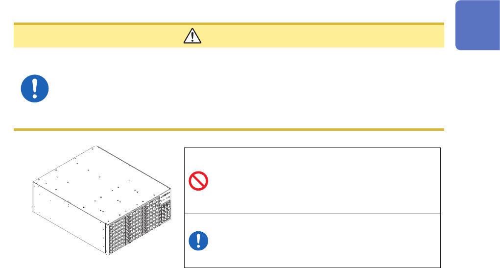
• Do not place the instrument on an unstable table.
• Do not place the instrument on an inclined
surface.
• Do not stack the multiple instruments.
• Vents must not be blocked.
• To prevent overheating, be sure to leave 5 cm
(2 inches) around the instrument.
• The instrument should be operated only with the
bottom side downwards.
5 cm or wider
10
Operation Precautions
Handling the instrument and modules
DANGER
• Do not use the modules or the cables to measure circuits that exceed those
ratings or specications. Damage to the instrument or overheating can cause
bodily injury.
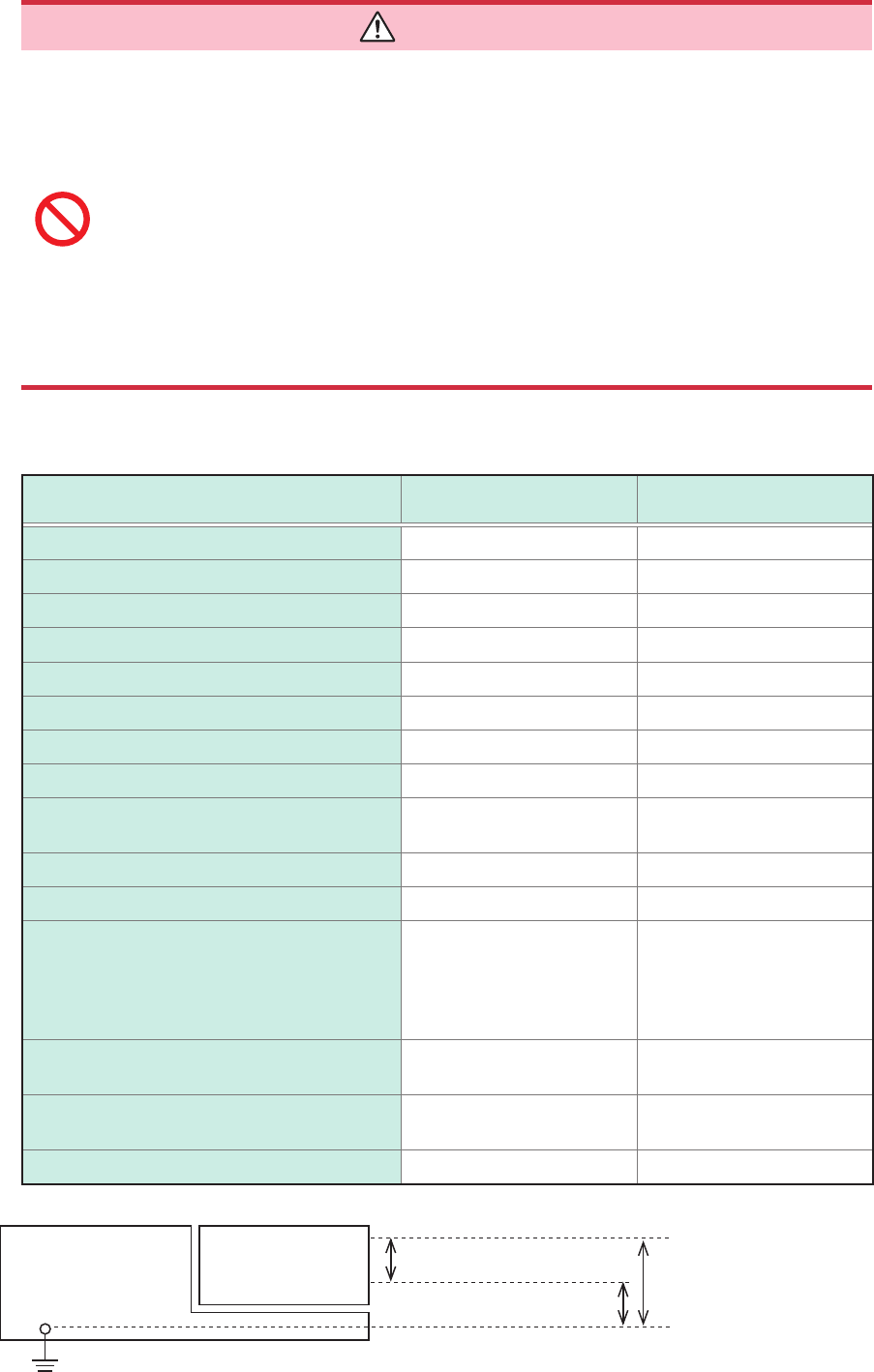
• The maximum input voltage and maximum rated voltage to earth of the modules
and connection cords are shown in the following table. To avoid an electric
shock and damage to the instrument, ensure that input voltage never exceeds
these limits. The lower maximum input voltage of the module or connection
cord must be used. Measuring a voltage exceeding this value can cause
damage to the instrument, resulting in bodily injury. The same applies to the
maximum rated voltage to earth using an input attenuator for the measurement.
Ensure that the connection does not allow the input voltage to exceed the
maximum rated voltage to earth.
Refer to “5.2 Specications of the Options” (p. 101).
Rating of input modules
Modules Maximum input voltage
Maximum rated voltage to
earth
Model 8966 Analog Unit 400 V DC 300 V AC/DC (CAT II)
Model 8967 Temp Unit – 300 V AC/DC (CAT II)
Model 8968 High Resolution Unit 400 V DC 300 V AC/DC (CAT II)
Model U8969 Strain Unit – 30 V rms / 60 V DC
Model 8970 Freq Unit 400 V DC 300 V AC/DC (CAT II)
Model 8971 Current Unit – Non-isolated
Model 8972 DC/RMS Unit 400 V DC 300 V AC/DC (CAT II)
Model 8973 Logic Unit – Non-isolated
Model U8974 High Voltage Unit
1000 V DC
700 V AC
1000 V AC/DC (CAT III)
600 V AC/DC (CAT IV)
Model U8975 4ch Analog Unit 200 V DC 300 V AC/DC (CAT II)
Model U8977 3CH Current Unit – Non-isolated
Model U8978 4CH Analog Unit
40 V DC (Direct input)
400 V DC (with Model 9665
10:1 Probe used)
30 V AC, 60 V DC
(Direct input)
300 V AC/DC (CAT II)
(with Model 9665 10:1
Probe used)
Model U8979 Charge Unit 40 V DC
30 V AC
60 V DC
Model
MR8990
Digital Voltmeter Unit 500 V DC 300 V AC/DC (CAT II)
Model U8991 Digital Voltmeter Unit 100 V DC 100 V AC/DC
ModulesModel MR8740T
High
Low
Maximum input voltage
Maximum rated voltage
to earth

11
Operation Precautions
Rating of generator modules
You can mixedly install generator modules and measurement modules in the instrument.
Intended use Model name Number of
channels
Maximum output
frequency
Output voltage
For generating sine
wave and DC
Model MR8790
Waveform Generator
Unit
4 20 kHz −10 V to 10 V
For generating pulse
Model MR8791
Pulse Generator Unit
8 20 kHz
TTL level
(amplitude: 0 to 5 V)
Open-collector output
For generating DC
voltage, DC current,
and resistance
generation
Model U8794
VIR Generator Unit
8
Voltage: −0.1 V to 5.3 V
Current: −5 mA to 5 mA
Resistance: 10
Ω
to 1 M
Ω
Ratings of connection cords
Connection Cord Maximum input voltage Maximum rated voltage to earth
Model L9197 Connection Cord 600 V AC/DC
600 V AC/DC (CAT III)
300 V AC/DC (CAT IV)
Model L9198 Connection Cord
(for measuring low-voltage)
300 V AC/DC
600 V AC/DC (CAT II)
300 V AC/DC (CAT III)
Model L9217 Connection Cord
Model L9790 Connection Cord 600 V AC/DC
• With Model L9790-01 Alligator Clip or
Model 9790-03 Contact Pin attached
600 V AC/DC (CAT II)
300 V AC/DC (CAT III)
• With Model 9790-02 Grabber Clip
attached
300 V AC/DC (CAT II)
150 V AC/DC (CAT III)
Model 9322 Differential Probe
2000 V DC
1000 V AC
• With grabber clips attached
1500 V AC/DC (CAT II)
600 V AC/DC (CAT III)
• With alligator clips attached
1000 V AC/DC (CAT II)
600 V AC/DC (CAT III)
Model L4940 Connection Cord 1000 V DC*
• With Model L4935 Alligator Clip Set or
Model L4932 Test Pin Set attached
600 V AC/DC (CAT IV)
1000 V AC/DC (CAT III)
• With Model 9243 Grabber Clip or
Model L4936 Bus Bar Clip Set attached
600 V AC/DC (CAT III)
• With Model L4937 Magnetic Adapter
Set attached
1000 V AC/DC (CAT III)
• With Model L4934 Small Alligator Clip
Set attached
300 V AC/DC (CAT III)
600 V AC/DC (CAT II)
Model P9000-01 Differential Probe
1000 V AC/DC 1000 V AC/DC (CAT III)
Model P9000-02 Differential Probe
Model 9166 Connection Cord
30 V AC
60 V DC
For inputting voltage into Model U8979
*: When Model U8974 High Voltage Unit is used