MR8740T_Quick guide_eng_20191016H.pdf - 第169页
163 A Acceleration sensor .................................................. 46 Aliasing ..................................................................... 69 Auto-range ...............................................…
162
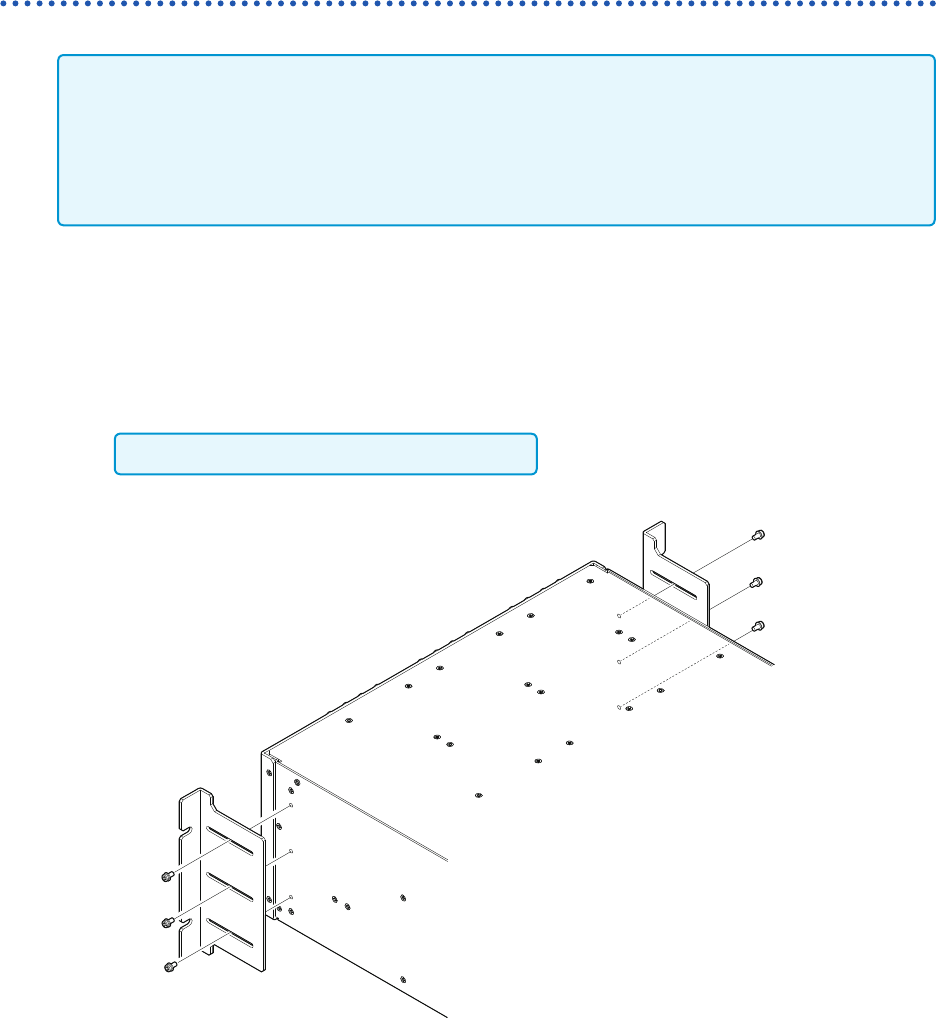
Mounting the instrument in a rack
How to secure the rack-mount brackets
• Support the instrument by installing commercially-available support angles in the rack because
the instrument is heavy.
• Leave 20 mm or more from the bottom side and the sides that have the vents (upper, right, left,
and bottom sides).
• If you need the screws (M4 × 8 mm), please contact your authorized Hioki distributor or
reseller.
EIA
1
Check that the instrument is turned off and remove any cables and the power cord.
2
Secure each rack-mount bracket using three screws (M4 × 8 mm).
Do not use any screws longer than 8 mm.

163
A
Acceleration sensor .................................................. 46
Aliasing ..................................................................... 69
Auto-range ................................................................ 78
B
Blank panel ............................................................... 12
BMP .......................................................................... 77
Built-in drive .............................................................. 57
C
Calibration ................................................................ 65
Channel number ....................................................... 35
Clock......................................................................... 62
Clock setting ............................................................. 62
Comment .................................................................. 71
Computer ............................................................ 55, 84
Connection cord ................................................. 36, 38
Current sensor .......................................................... 43
D
Date and time ........................................................... 62
Disposal
Lithium battery..................................................... 159
E
Error ........................................................................ 149
External control terminal ........................................... 53
External trigger ......................................................... 54
EXT.SMPL ................................................................ 19
EXT.TRIG ................................................................. 19
F
Format ...................................................................... 59
H
Help function............................................................. 32
I
IN1 ............................................................................ 19
IN2 ............................................................................ 19
Initializing the instrument ........................................ 147
L
LAN........................................................................... 55
Level trigger .............................................................. 73
Logic probe ............................................................... 17
Low-pass lter .......................................................... 72
L.P.F ......................................................................... 72
M
Maximum input voltage............................................. 10
Maximum rated voltage to earth ............................... 10
Measurement range ................................................. 71
Memory check ........................................................ 154
Model U8794 VIR Generator Unit............... 37, 51, 137
Model U8969 Strain Unit .......................................... 41
Module ...................................................................... 34
Mounting the instrument in a rack .......................... 161
Mouse ....................................................................... 29
O
Option ......................................................................... 5
OUT1 ........................................................................ 19
OUT2 ........................................................................ 19
P
Probe ratio ................................................................ 72
R
Recording length ...................................................... 68
S
Sampling rate ........................................................... 68
Saving data
Screenshot ............................................................ 76
Scrolling through waveforms .................................... 83
Selective save .......................................................... 76
Self-check ............................................................... 154
Start button ............................................................... 60
Start icon .................................................................. 75
Stop icon................................................................... 75
Storage device.......................................................... 57
T
Thermocouple........................................................... 40
Trace cursor ............................................................. 81
Trigger ...................................................................... 73
TRIG.OUT ................................................................ 19
Type (Saving type).................................................... 77
U
USB ash drive ......................................................... 57
Index
Index
Index

164
Index
W
Warm-up ................................................................... 60
Warning .................................................................. 150
Waveform viewer ...................................................... 84
Z
Zero-adjustment ....................................................... 63
Zoom in..................................................................... 83
Zoom out .................................................................. 83