MR8740T_Quick guide_eng_20191016H.pdf - 第59页
53 Connecting the External Control T erminals 2.3 Connecting the External Control T erminals This section describes the procedure and the external control terminal function to externally control the instrument. Connectin…
52
Attaching Connection Cords
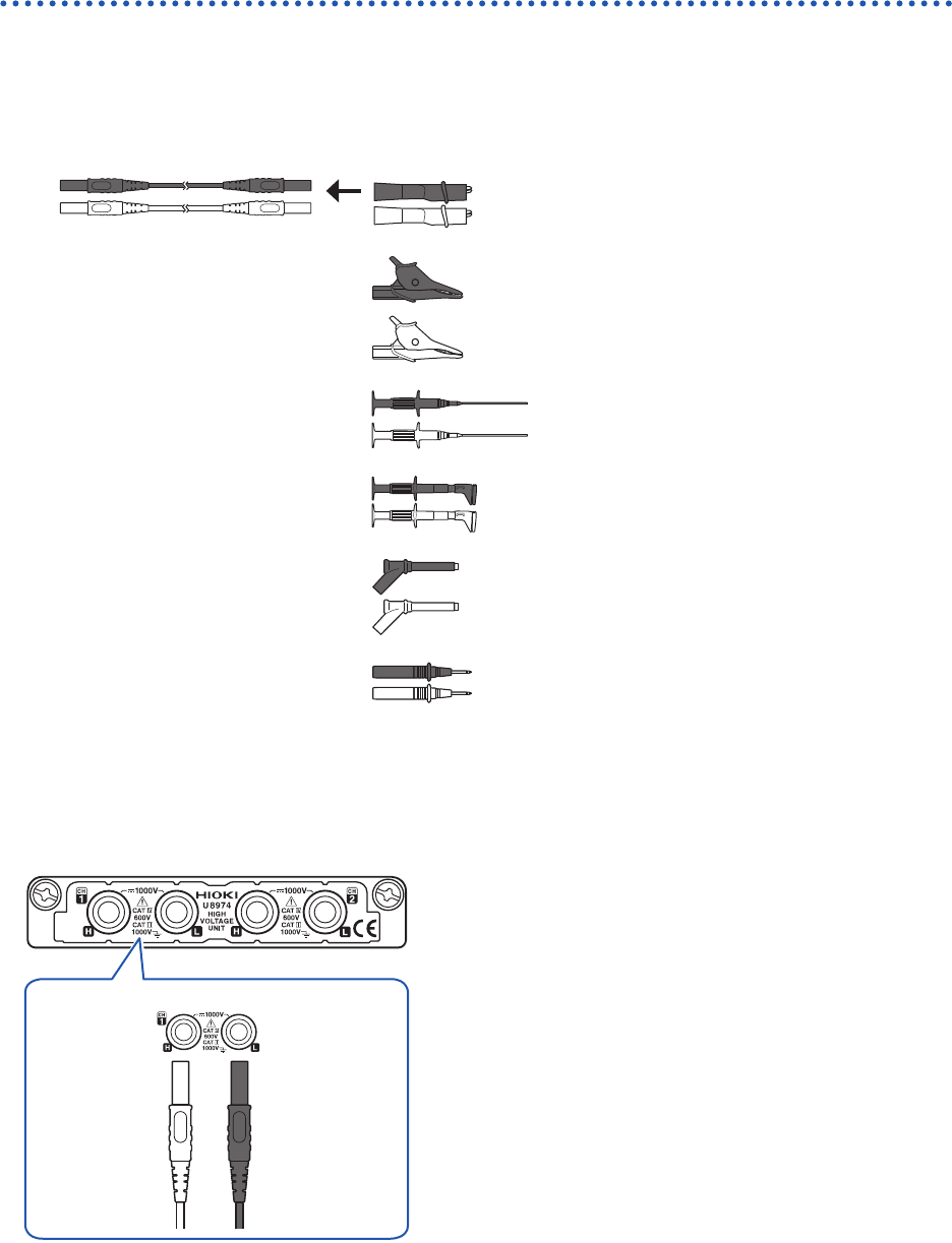
Connection cable (high voltage)
Connect Model L4940 Connection Cable Set to Model U8974 High Voltage Unit. Choose
appropriate connection cord tips based on the maximum input voltage and terminal type.
Required item: Model L4940 Connection Cable Set
Model L4934* Small
Alligator Clip Set
CAT III 300 V
CAT II 600 V
Model L4935 Alligator Clip
Set
CAT III 1000 V
CAT IV 600 V
Model 9243 Grabber Clip CAT III 1000 V
Model L4936 Bus Bar Clip
Set
CAT III 600 V
Model L4937 Magnetic
Adapter Set
CAT III 1000 V
Model L4932 Test Pin Set CAT III 1000 V
CAT IV 600 V
* Using Model L4934 requires Model L4932.
How to connect the thermocouple
Model U8974 High Voltage Unit
Red Black
H L
1
Connect the plugs of the connection cord to
the banana jacks on the module.
Connect the plugs to the banana jacks of their respective
colors.
2
Insert the accessory clips into the clip ends of
the connection cord.
3
Connect the connection cord clips to a
measuring object.
53
Connecting the External Control Terminals
2.3 Connecting the External Control Terminals
This section describes the procedure and the external control terminal function to externally
control the instrument. Connecting the external control terminals with external devices allows the
instrument to start and stop measurement.
The term “external control terminals” is used to refer to all of these terminals collectively.
Refer to “Before connecting the instrument to external equipment” (p. 19).
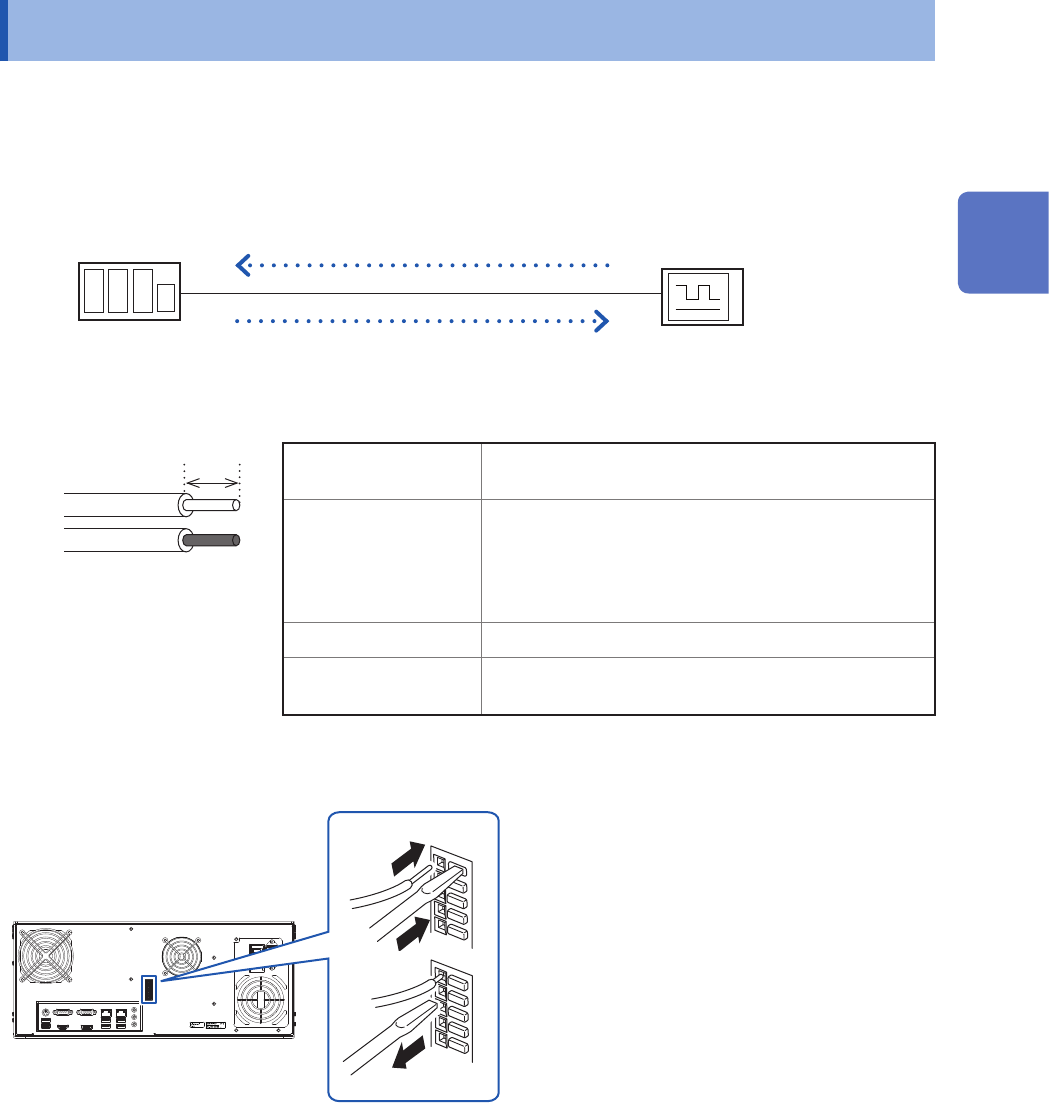
Model MR8740T
External device
Wires to be connected
Recommended wire Solid wire: 0.65 mm in diameter (AWG22)
Stranded wire: 0.32 mm
2
(AWG22)
Acceptable wire Solid wire: 0.32 mm to 0.65 mm in diameter
(AWG28 to AWG22)
Stranded wire: 0.08 mm
2
to 0.32 mm
2
(AWG28 to AWG22)
Strand diameter: 0.12 mm or more (per wire)
Stripped length 9 mm to 10 mm
Button pressing tool Flat-blade screwdriver
(shaft diameter: 3 mm, tip width: 2.6 mm)
Solid wire
Stranded wire
10 mm
How to connect wires
Rear side
1
2
3
1
Depress the terminal button
using a tool, such as a at-blade
screwdriver.
2
Insert the wire into the wire
connection hole while depressing
the button.
3
Release the button.
The wire is locked.
2
Preparing for Measurement
54
Connecting the External Control Terminals
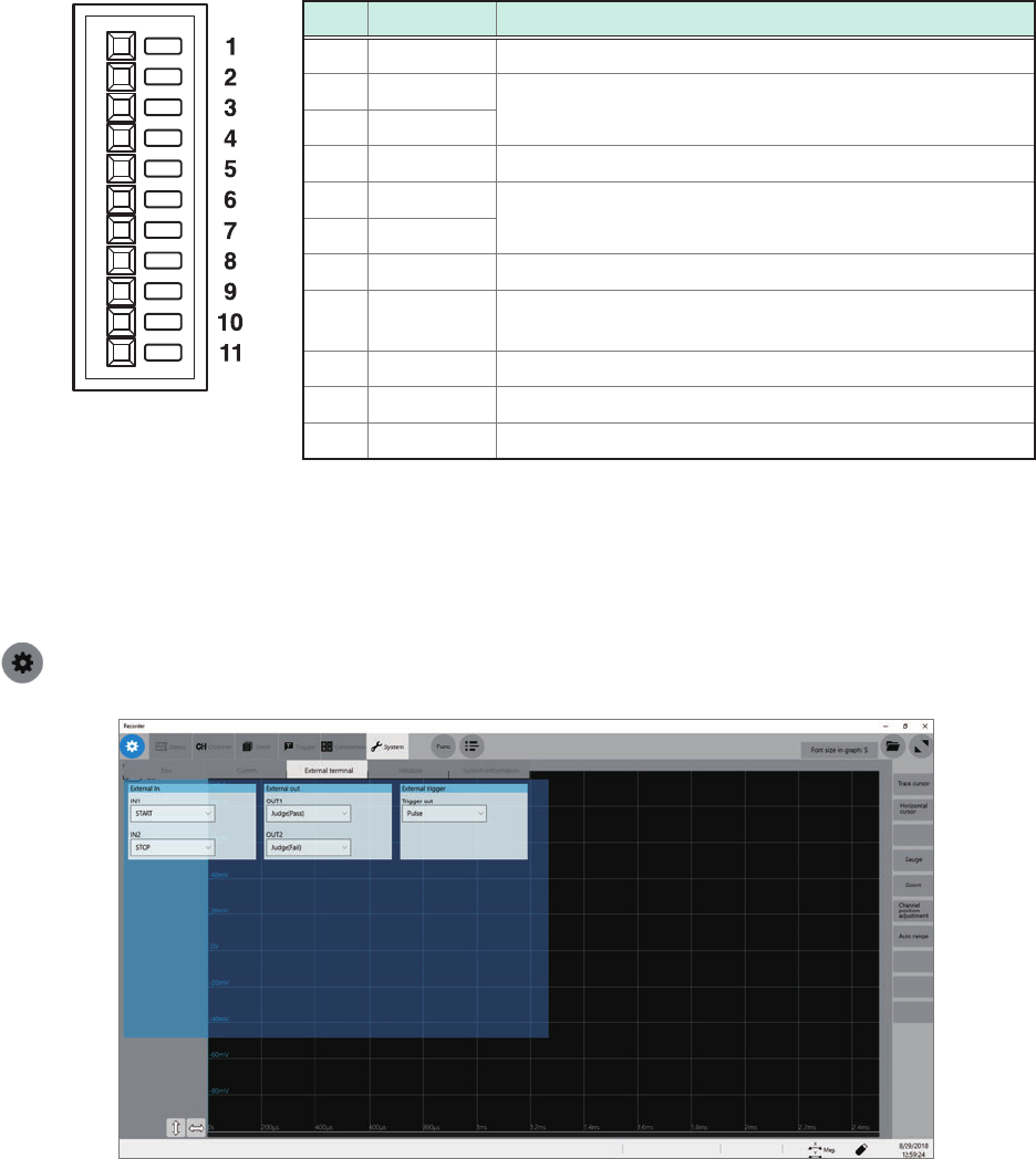
Terminal block
No. Pin name Operation
1 GND –
2 IN1
Starts/stops measurement, saves data les, aborts
measurement, enters events
3 IN2
4 GND –
5 OUT1
Outputs signals indicating judgments and status (error,
busy, waiting for a trigger)
6 OUT2
7 GND –
8 EXT.TRIG
The instrument is triggered when an external signal is
inputted as a trigger source.
9 TRIG.OUT Outputs a signal when the instrument is triggered.
10 GND –
11 EXT.SMPL Input a external sampling signal.
How to congure the external control terminal settings
On the [External terminal] screen, you can congure the following terminal: the external input (IN1,
IN2), external output (OUT1, OUT2), and trigger output (TRIG.OUT). Use the [Trigger] screen to
congure the external trigger (EXT.TRIG) setting.
> [System] > [External terminal]