MR8740T_Quick guide_eng_20191016H.pdf - 第86页
80 Measuring Signals With the Auto-range Setting

79
Measuring Signals With the Auto-range Setting
• Be careful when performing auto-range measurement while using the TRIG OUT signals. Starting
a measurement with the auto-range setting outputs a trigger signal from the TRIG.OUT terminal.
• Input signals (waveforms) before starting a measurement with the auto-range setting. The auto-
range function changes the setting depending on a signal inputted on the start of execution.
• When an input signal acquired across the channel lowest-numbered among the channels with
the [Display] button set to [On] has an extremely small level, the sampling rate is specied
depending on the input signal of the next lowest-numbered channel.
• If the range setting fails for every channel with the [Display] button set to [On], the instrument
displays a warning message and cancels the measurement.
• When the auto-save is set to on, the instrument saves the data after specifying the setting value
of the auto-range.
• The instrument cannot choose an adequate automatic range for a signal with a frequency of
lower than 10 Hz. Manually choose a measurement range.
• The auto-range function is not available for the following modules:
Model 8967 Temp Unit
Model U8969 Strain Unit
Model 8970 Freq Unit
Model MR8990 Digital Voltmeter Unit
Model U8991 Digital Voltmeter Unit
Model 8973 Logic Unit
3
Measurement Method
80
Measuring Signals With the Auto-range Setting
81
4
Analysis Method
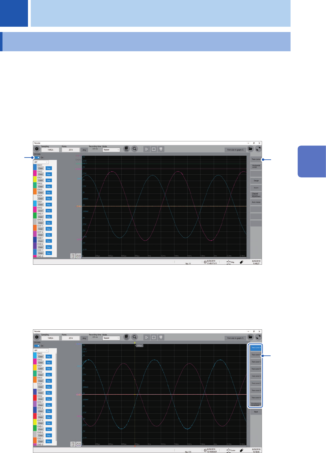
4.1 Reading Measured Values (Trace Cursors)
You can read measured values (scaled values when the scaling is used) using trace cursors on the
waveform screen. The instrument can simultaneously display up to eight trace cursors. You can
read differences in times and measured values between any two cursors you choose from among
all cursors.
For information about other types of cursors than the trace cursor, refer to “2 Operating the
Waveform Screen and Analyzing Data” in Instruction Manual.
1
Set [CH Info] toggle switch to [On].
Click [CH Info] toggle switch to switch between [On] and [Off] for the information display setting of each
channel.
1
2
2
Click [Trace cursor].
3
Choose one or more cursors to be displayed from among
[Trace cursor A]
through
[Trace
cursor H]
by tapping them.
The chosen trace cursors are displayed on the waveform screen.
Drag the trace cursors on the waveform screen to move them.
3
4 Analysis Method
4
Analysis Method