MR8740T_Quick guide_eng_20191016H.pdf - 第26页
20 How to Refer to This Document How to Refer to This Document How to open a screen Indicates the order of clicking the screens. The button represents the setting key . Procedure numbers Numbered same as a corresponding …
19
Operation Precautions
Before connecting the instrument to external equipment
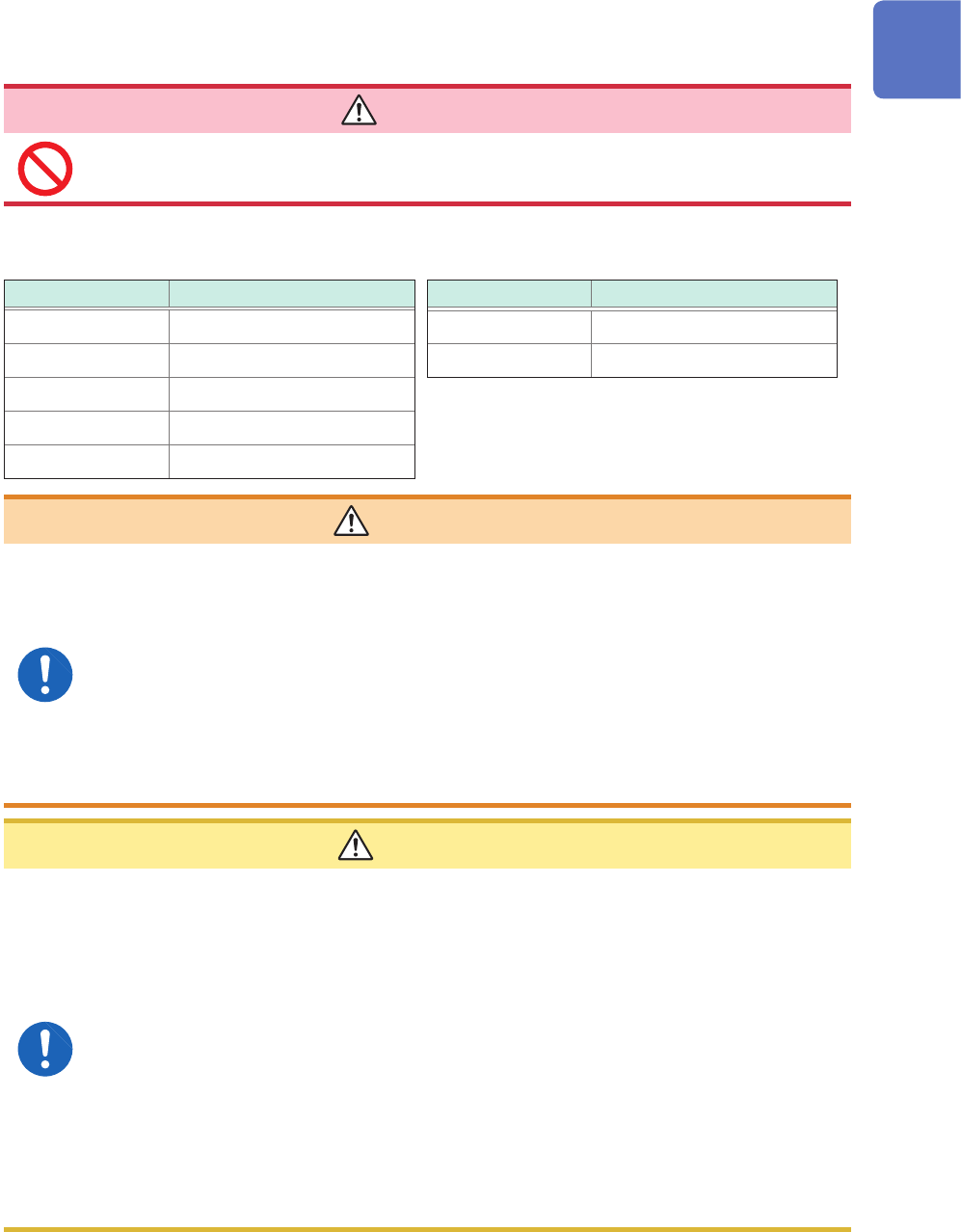
DANGER
To avoid electrical hazards and damage to the instrument, do not apply voltage
exceeding the rated maximum to the external control terminals.
Model MR8740T
I/O terminal Maximum input voltage
IN1 10 V DC
IN2 10 V DC
OUT1 50 V DC, 50 mA, 200 mW
OUT2 50 V DC, 50 mA, 200 mW
TRIG.OUT 50 V DC, 50 mA, 200 mW
I/O terminals Maximum input voltage
EXT.TRIG 10 V DC
EXT.SMPL 10 V DC
WARNING
To avoid an electric shock or damage to the equipment, always observe the
following precautions when connecting your external equipment to external
control terminals.
• Always turn off the instrument and any equipment to be connected before
making connections.
• Be careful to avoid exceeding the ratings of the external control terminals.
• Properly isolate the devices and systems to be connected to the external
control terminals from one another.
Always turn both devices off before connecting and disconnecting an interface
connector. This may cause an electric shock.
CAUTION
• Use a common ground to both the instrument and the connected equipment. Using
different ground circuits will result in a ground potential difference between the
instrument and the connected equipment. If the communications cable is connected
while such a potential difference exists, it may result in equipment malfunction or
failure.
• Before connecting or disconnecting any communication cable, always turn off the
instrument and your device to be connected. Failure to do so could result in an
equipment malfunction or damage to the equipment.
• After inserting the connector, securely tighten the screws of the connector. Failure to
do so could result in an equipment malfunction or damage to the equipment.
• To prevent damage to the equipment, use the recommended type of wires to connect
your external equipment to the external control terminal, or otherwise ensure that the
wires have sufcient withstand voltage and current capacity.
Refer to “2.3 Connecting the External Control Terminals” (p. 53).
20
How to Refer to This Document
How to Refer to This Document
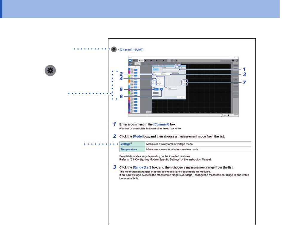
How to open a screen
Indicates the order of clicking the
screens.
The button
represents the
setting key.
Procedure numbers
Numbered same as a
corresponding step-by-step
instruction.
Options and explanations
Describes selectable settings
when an item is clicked.
The icon
indicates the default
setting of the item.
21
1
Overview
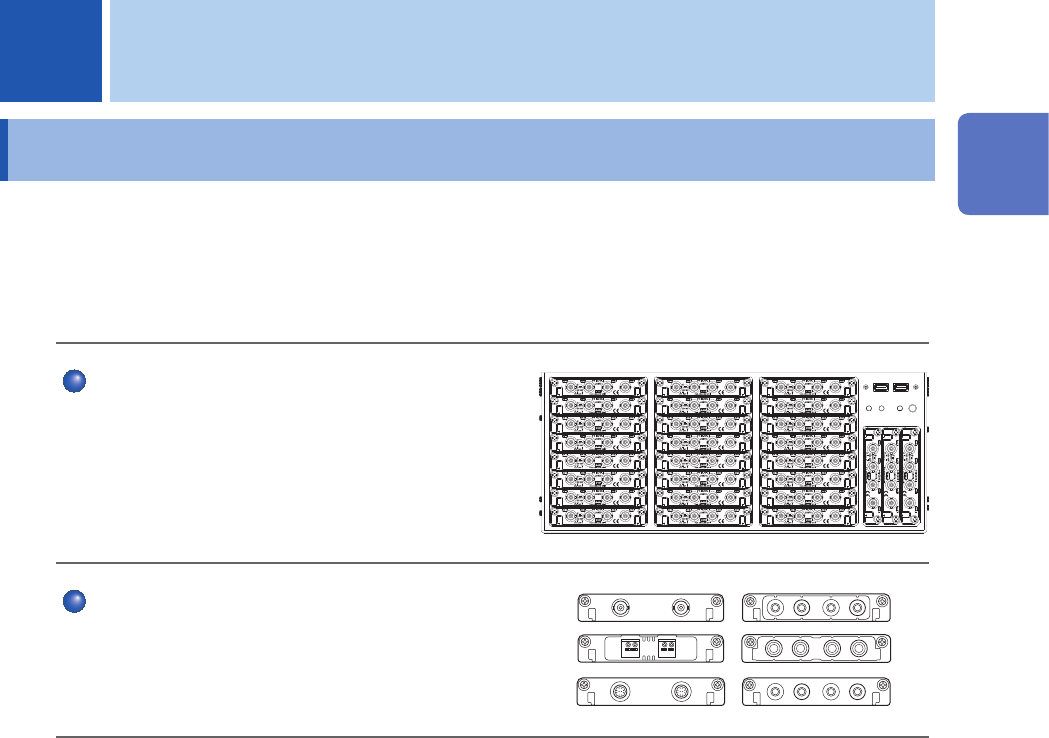
1.1 Product Overview and Features
This recorder allows you to observe a wide range of waveforms from low-speed signals to high-
speed waveforms.
You can mainly use this instrument for analyzing test and evaluation results of various products and
troubleshooting those products.
Multichannel simultaneous sampling
This instrument can simultaneously measure signals
across up to 108 channels.
Extensive line of measurement modules
Many types of measurement modules let the
instrument measure a variety of signals that include
voltage, current, temperature, and frequency.
1 Overview
1
Overview