MR8740T_Quick guide_eng_20191016H.pdf - 第5页
i 2.7 Setting the Clock .................................. 62 2.8 Regulating the Zero Position (Zero-Adjustment) ................................ 63 2.9 Executing Calibration (For the Instrument With Model MR8990 Install…
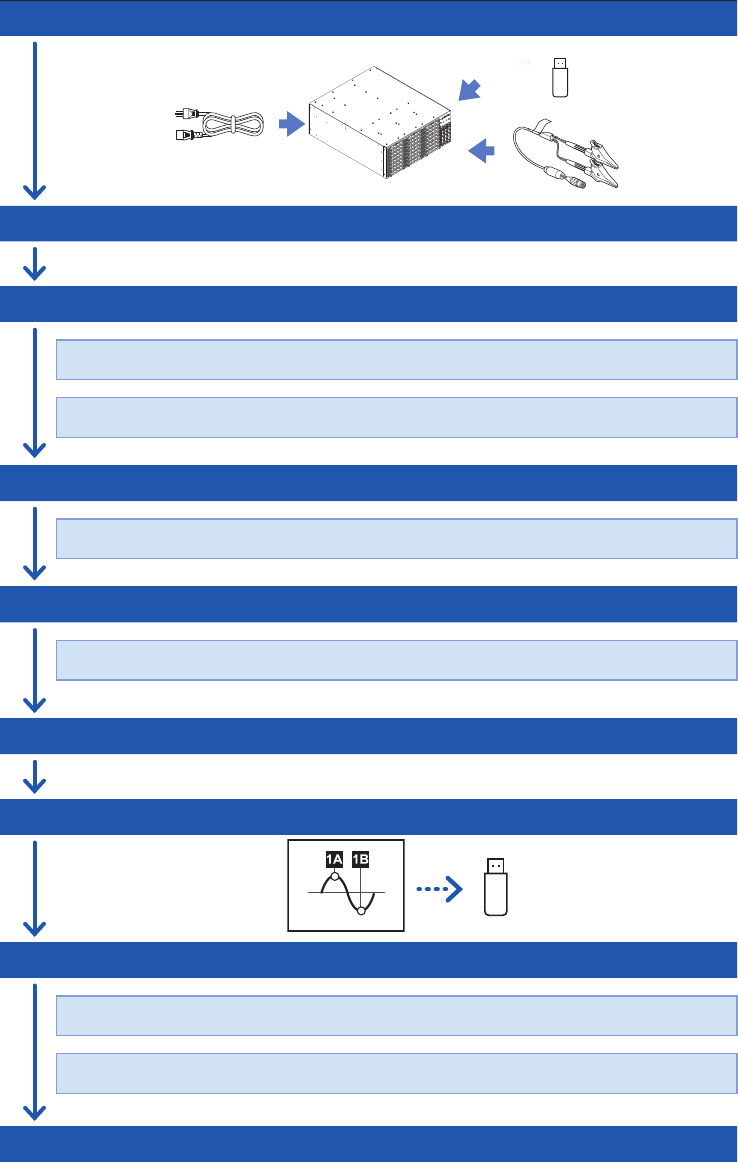
Measurement Procedure
The basic measurement procedure is as follows. For advanced use, refer to the Instruction Manual
(PDF) in the accompanying CD.
Preparing for measurement
(p. 33)
Inspecting the instrument before measurement
(p. 67)
Conguring the basic settings for measurement
(p. 68)
Choose a sampling rate.
Choose a recording length (shot).
Conguring the input channel settings
(p. 70)
Congure the analog channel settings.
Conguring the trigger settings
(p. 73)
Congure the trigger settings.
Starting/Stopping measurement
(p. 75)
Saving measured data les
(p. 76)
Analyzing waveforms
(p. 81)
Scroll through, zoom in, and zoom out waveforms.
Read measured values (with the trace cursors).
Finishing the measurement

i
2.7 Setting the Clock
..................................62
2.8 Regulating the Zero Position
(Zero-Adjustment)
................................63
2.9 Executing Calibration
(For the Instrument With Model
MR8990 Installed)
................................65
3 Measurement Method 67
3.1 Inspection Before Measurement
........67
3.2 Setting Measurement Conditions
.......68
Sampling rate setting guideline
..................69
3.3 Conguring the Input Channel
settings
...................................................70
Analog channel
.........................................71
3.4 Conguring the Level Trigger
Settings
..................................................73
3.5 Starting/Stopping Measurement
.........75
3.6 Saving Data Consisting of Items
Selected
.................................................76
3.7 Measuring Signals With the Auto-
range Setting
.........................................78
4 Analysis Method 81
4.1 Reading Measured Values
(Trace Cursors)
.....................................81
4.2 Handling Waveforms
............................83
Scrolling through waveforms
.....................83
Zooming in and out waveforms
..................83
4.3 Loading Data With Your Computer
(Wave Viewer)
.......................................84
5 Specications 87
5.1 Specications of Model MR8740T
.....87
General specications
...............................87
Trigger
......................................................92
Waveform screen
......................................94
Setting screen
..........................................95
File
...........................................................97
Performing calculation
...............................98
Waveform search
......................................99
Others
......................................................99
5.2 Specications of the Options
............101
Model 8966 Analog Unit
..........................101
Model 8967 Temp Unit
............................103
Model 8968 High Resolution Unit
............105
Model U8969 Strain Unit
.........................107
Model 8970 Freq Unit
.............................109
Model 8971 Current Unit
......................... 111
Model 8972 DC/RMS Unit
.......................113
Model 8973 Logic Unit
............................115
Contents
Introduction
........................................................1
Conrming Package Contents
........................4
Safety Information
............................................6
Operation Precautions
.....................................8
How to Refer to This Document
...................20
1 Overview 21
1.1 Product Overview and Features
.........21
1.2 Name and Function of Each Part
.......22
1.3 Screen
....................................................26
Screen conguration
.................................26
Explanation of each screen
.......................27
1.4 Basic Operation
....................................29
Mouse operation
.......................................29
Changing screens and settings
.................30
Help Function
(Displaying Instruction Manual)
.................32
2 Preparing for
Measurement
33
2.1 Installing and Removing Modules
......34
Allocation of modules and channels
...........35
2.2 Attaching Connection Cords
...............36
Connection cables
(For measuring voltage, frequency,
or rotation speed, and obtaining
accumulations)
.........................................38
Thermocouple (Temperature)
....................40
Strain gauge transducer
............................41
Current sensor
..........................................43
Acceleration sensor
..................................46
Logic probe (Measuring logic signals)
........48
Connection cable
(For precisely measuring voltage)
..............48
Outputting waveforms
...............................49
Outputting pulse waveforms
......................50
Outputting voltage, current, and
resistance
.................................................51
Connection cable (high voltage)
................52
2.3 Connecting the External Control
Terminals
...............................................53
2.4 Connecting the Instrument with
computers
..............................................55
2.5 Preparing Storage Devices
(Recording Media)
................................57
USB ash drive
.........................................57
Built-in drive
..............................................57
Removing storage devices
........................58
Formatting storage devices
.......................59
2.6 Supplying Power to the Instrument
....60
Turning on the instrument
.........................60
Turning off the instrument
..........................61
7
6
5
4
3
2
1
Index

Contents
ii
Model MR8990 Digital Voltmeter Unit
......116
Model U8974 High Voltage Unit
...............118
Model U8975 4ch Analog Unit
.................120
Model U8977 3CH Current Unit
(The rmware of ver. 2.00 or later is
required to install the module.)
................122
Model U8978 4CH Analog Unit
(The rmware of ver. 2.00 or later is
required to install the module.)
................125
Model U8979 Charge Unit
(The rmware of ver. 2.00 or later is
required to install the module.)
................127
Model U8991 Digital Voltmeter Unit
.........130
Model MR8790 Waveform Generator
Unit
........................................................132
Model MR8791 Pulse Generator Unit
......134
Model U8794 VIR Generator Unit
............137
6 Maintenance and
Service
143
6.1 Troubleshooting
..................................145
Before sending the instrument for
repair
......................................................145
6.2 Initializing the Instrument
...................147
6.3 Message
..............................................148
Error messages
......................................149
Warning messages
.................................150
6.4 Self-check
............................................154
Memory check
........................................154
LAN check
..............................................155
Media check
...........................................157
System conguration check
.....................158
6.5 Cleaning the Instrument
....................159
6.6 Disposing of the Instrument
(Removing the lithium battery)
..........159
7 Appendix 161
7.1 Mounting the instrument in a rack
....161
Rack-mount brackets
..............................161
How to secure the rack-mount
brackets
.................................................162
Index 163
Warranty Certicate